Do you have a question about the MKS 670B and is the answer not in the manual?
Definitions of WARNING, CAUTION, and NOTE messages.
Defines symbols present on the equipment itself.
General safety precautions for instrument operation and handling.
Overview of the MKS Type 670B High Accuracy Signal Conditioner.
Explains the structure and content of the instruction manual.
Details conventions used for inputs, outputs, keys, and modes.
Information on MKS maintenance, repair services, and contact.
Procedure for safely unpacking the MKS Type 670B instrument.
List of standard equipment included with the Type 670 unit.
Details system interface and remote communication cables.
Specifies MKS cables for connecting to transducers and multiplexers.
Lists cables for RS-232 or IEEE-488 communication.
Guidelines for manufacturing or selecting shielded cables for MKS equipment.
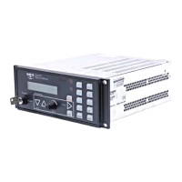
Diagrams and measurements of the front and side views of the 670 instrument.
Diagram and measurements of the top view of the 670 instrument.
Describes the front panel layout including display, keys, LEDs, and indicators.
Details the function of the Key Lock switch for operation modes.
Covers I/O, serial, IEEE-488, signal connectors, and power entry.
Details the Head and Signal connectors on the Signal Conditioner Board.
Describes the power entry module and rear panel identification labels.
Introduces the 670 functionality and how to perform tasks.
Explains the color coding of front panel keys for functional association.
Describes how to scroll through menu screens using arrow keys.
Details how to select options and enter values in menus.
Explains how the instrument handles invalid data entries.
Describes the main pressure display and other information shown.
Explains how to select channels, especially with a multiplexer.
Details how to use the SETUP key to configure operational parameters.
Configures the filter used to reduce noise in the pressure signal.
Allows selection of power supply to a heated pressure transducer.
Sets the units for pressure readings and remote reporting.
Sets the full scale reading of the pressure transducer in conjunction with units.
Sets temperature compensation for transducers with selectable temperatures.
Smooths pressure readings by averaging multiple data points.
Configures baud rate, data bits, and parity for RS-232 communication.
Configures the IEEE-488 device address for remote communication.
Configures two alarm trip points, defining high/low values and relay states.
Defines high/low trip point values, including disabling trip points.
Explains how to adjust hysteresis values for trip points to prevent relay chatter.
Sets the normal state of trip point relays (energized or de-energized).
Assigns channels (1-3) for each trip point, especially with a multiplexer.
Enables latching of trip points to maintain alarm state until cleared.
Configures the latch state (enabled/disabled) for trip points.
Accesses calibration information and performs Null and Full Scale calibration.
Procedure to eliminate zero errors inherent in the instrument.
Procedure to calibrate output span to an internal standard for gain errors.
Displays system check value for diagnostic purposes.
Allows zeroing the transducer from the 670 instrument across all ranges.
Enables or disables the zero calibration procedure.
Initiates the zero calibration procedure when enabled.
Describes how to zero the instrument remotely via I/O connector pins.
Explains autoranging and manual range selection features.
Step-by-step guide to connect and configure the 670 instrument for operation.
Details the cable connections between the 670 and 274 multiplexer.
Steps to configure the Type 274 multiplexer for use with the 670 instrument.
Details configuration steps for the 670 when connected to a 274 multiplexer.
Explains how to disable a trip point by setting its value to ±105%.
Procedure to release a latched trip point and maintain latch mode.
Details how to adjust hysteresis values for trip points to prevent relay chatter.
Shows how to display heater power supply alongside pressure readings.
Introduces RS-232 option and its operation modes.
Lists and explains RS-232 communication parameters like baud rate and parity.
Defines RS-232 message syntax, commands, and requests.
Format and structure of commands sent to the 670 instrument via RS-232.
Format of requests sent to the 670 instrument to retrieve information.
Format of responses from the 670 instrument to commands and requests.
Divides RS-232 messages into groups for parameters, channels, and diagnostics.
Commands and requests for global functions like mode and channel selection.
Commands and requests for channel-specific functions like response time and units.
Commands for setting trip point values, hysteresis, and latch modes.
Commands for checking software version and I/O connector status.
Introduces IEEE-488 option and its compliance with standards.
Explains the Key Lock switch for enabling IEEE-488 remote operation.
Describes the IEEE-488 compliant functions and commands.
Specifies the fixed buffer length for IEEE-488 communications.
Details how to set the IEEE-488 device address.
Explains the use of status registers for monitoring instrument status.
Describes the Standard Event Status Register and its bit functions.
Describes the Status Byte Register and its bit functions.
Explains how to configure enable registers for generating Service Requests.
Lists standard and device-dependent messages for controlling the instrument.
Clears all status data structures and registers.
Determine instrument task status (performing or idle).
Functions as a 'no operation' command, controlling command execution flow.
Queries the instrument for manufacturer, model, and firmware level.
Initializes the instrument, including bus and message exchange.
Performs an internal self-test and reports success or failure.
Details MKS specific commands for configuration and queries.
Explains typographical conventions for MKS device dependent messages.
Commands for setting active channel, mode, and calibration procedures.
Commands for setting scan, response time, heater, and compensation per channel.
Commands for setting trip point values, hysteresis, and relay states.
Commands for testing output signals and reading input bits on the I/O connector.
General checks for wear, damage, and fuse replacement.
Instructions for cleaning the instrument with a damp cloth.
Step-by-step guide for replacing the instrument's fuses.
Describes common problems and offers solutions for the 670 instrument.
Identifies causes and solutions for noisy pressure readings.
Diagnoses issues causing trip point relays to change state unexpectedly.
Addresses issues causing overrange pressure readings and provides diagnostic steps.
Procedure to isolate malfunctions between the cable and the instrument electronics.
Procedure to localize malfunctions within the instrument's electronics.
Details key performance parameters of the 670 instrument.
Specifications for display accuracy, linearity, and update rate.
Details compliance with EMC, Low-Voltage, and Safety Directives.
Details connectors, trip points, dimensions, and weight of the instrument.
Specifies operating temperature and humidity ranges.
Details power requirements and fuse types for the instrument.
Describes CB270-2 and CB670-1/CB670-2 cables for I/O connection.
Details the CB670-2 Y-cable, its connectors, and available functions.
Lists pin assignments for the 25-pin male connector of the Y-cable.
Lists pin assignments for the 25-pin female connector of the Y-cable.
| Brand | MKS |
|---|---|
| Model | 670B |
| Category | Industrial Equipment |
| Language | English |