Troubleshooting Cha
ter Ei
ht: Maintenance and Troubleshootin
134
8. Use the DVM to check the voltages at the transducer end of the cable.
Refer to Table 37 for the appropriate voltage values. Reference the DVM to pin H (2).
Transducer Cable Voltage Check
Transducer Cable
Pin Number
Voltage Function
I or (13) +12 to +13 Transducer electronics supply voltage
D or (14) +12 to +13 System Check command
J or (15) 6 Volts RMS Excitation voltage
Note that some transducer cables use numbers while others use letters.
Table 37: Transducer Cable Voltage Check
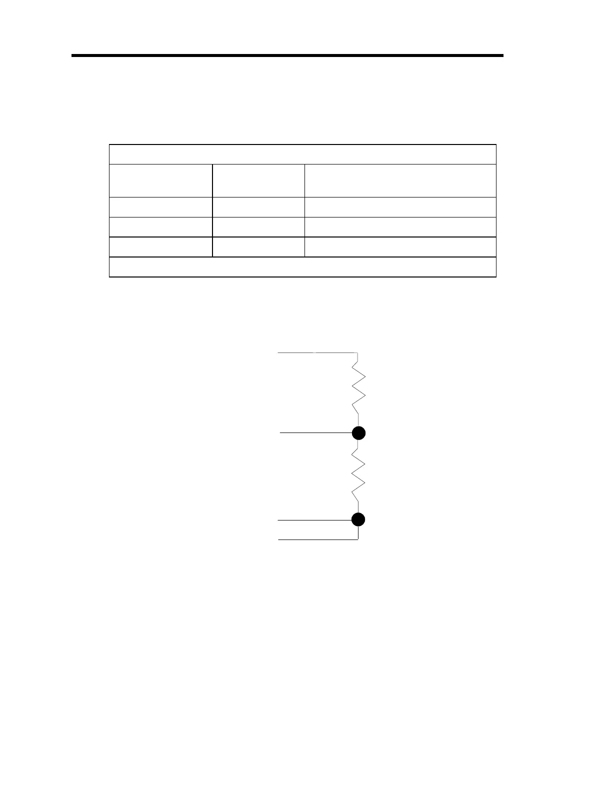
9. Connect two resistors to the transducer cable, as shown in Figure 19.
Pin J (15)
Pin A (7)
Pin B (6)
Pin H (2)
3
1
Figure 19: Two Resistors Added to the Transducer Cable
10. Press the [
CAL
] key to enter the calibration menu.
The system responds by displaying the calibration screen.
Artisan Technology Group - Quality Instrumentation ... Guaranteed | (888) 88-SOURCE | www.artisantg.com