The [TRIP POINTS] Key Cha
ter Four: Functional Overview
56
Hysteresis
Hysteresis is built into the operation of the two trip points to help compensate for the noise
inherent in all systems. Without hysteresis, the noise may cause the relays to repeatedly switch
states, a condition known as “relay chatter.” The amount of hysteresis can be adjusted separately
for each trip point.
Setting the hysteresis too high will create a
deadband
around the trip point. The deadband
prevents the trip point relay from responding to changes in the pressure signal around the trip
point. Ideally, the hysteresis should be close to, but not less than, the peak-to-peak noise. This
setting will provide maximum immunity from relay chatter while providing the best possible
accuracy. It may take some trial and error efforts to determine the smallest hysteresis setting
appropriate for your system to prevent relay chatter.
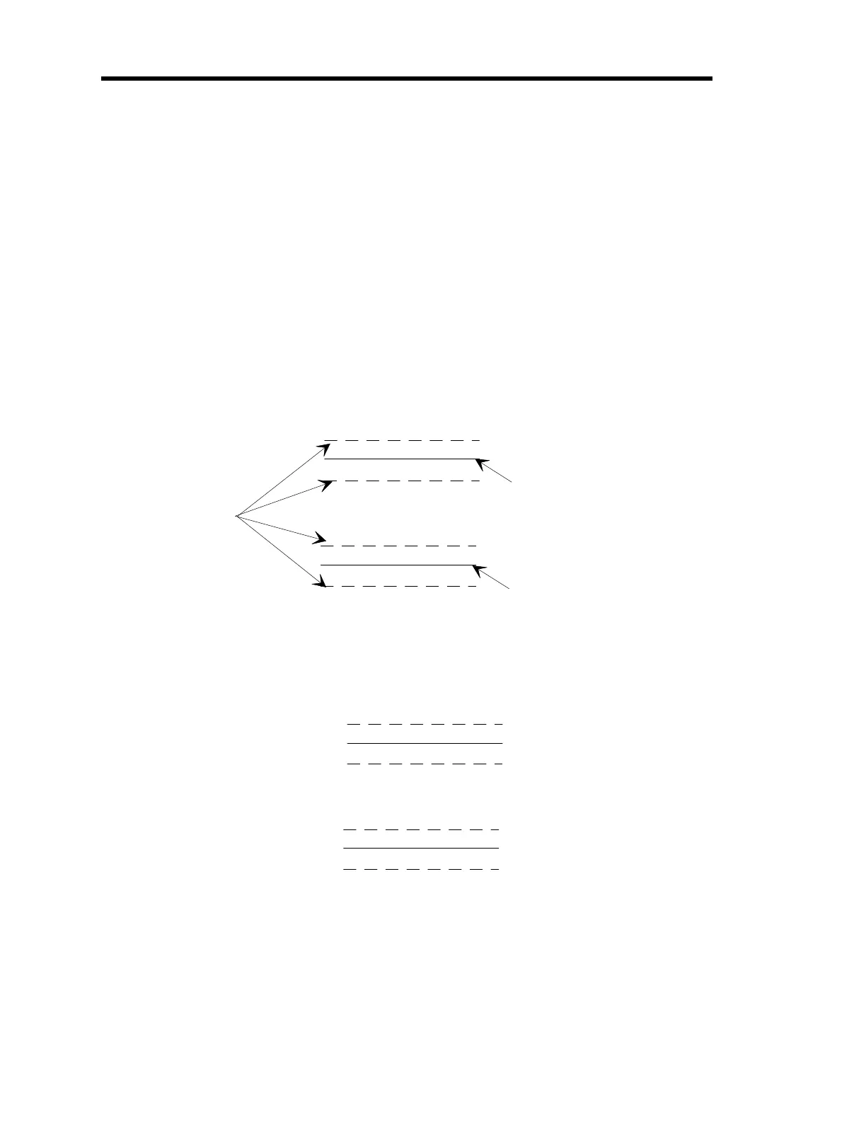
The hysteresis value is defined as a ±percent of the trip point value and can range from 0 to
10%. The 670 instrument adds the ± hysteresis value to the trip point value to create a hysteresis
band around the trip point, as shown in Figure 12.
Trip Point Hi
h Value
Trip Point Low Value
Hysteresis
Values
Figure 12: Hysteresis Bands Applied to the Trip Point Values
Example:
Setting the trip point high value to 100, the trip point low value to 50, and the
hysteresis entry to 1%, creates the hysteresis bands shown in Figure 13.
101
99
50.5
49.5
100
50
Figure 13: Hysteresis Bands and Trip Point Values
Therefore, the high trip point is activated when the pressure exceeds 101. It is deactivated when
the pressure drops below 99. The low trip point is activated when the pressure drops below 49.5.
It is deactivated when the pressure exceeds 50.5.
Artisan Technology Group - Quality Instrumentation ... Guaranteed | (888) 88-SOURCE | www.artisantg.com