List of Fi
ures
ix
List of Figures
Figure 1: Preferred Method.................................................................................................... 26
Figure 2: Alternate Method To Use When Cable Clamp is Not Available.............................. 26
Figure 3: Front View Dimensions.......................................................................................... 28
Figure 4: Side View Dimensions........................................................................................... 28
Figure 5: Top View Dimensions............................................................................................ 29
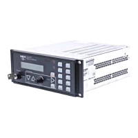
Figure 6: The Front Panel......................................................................................................31
Figure 7: The Rear Panel with RS-232 Communications....................................................... 33
Figure 8: The Rear Panel with IEEE-488 Communications.................................................... 33
Figure 9: Labels on the Rear Panel........................................................................................ 41
Figure 10: Serial Number Label............................................................................................. 41
Figure 11: Averaging with 5 Data Points............................................................................... 51
Figure 12: Hysteresis Bands Applied to the Trip Point Values............................................... 56
Figure 13: Hysteresis Bands and Trip Point Values ............................................................... 56
Figure 14: Autoranging on a 10 Volt Full Scale Signal.......................................................... 64
Figure 15: Connecting to a Single Pressure Transducer ......................................................... 67
Figure 16: Connecting to a Type 274 Multiplexer.................................................................. 69
Figure 17: IEEE-488 Registers.............................................................................................. 105
Figure 18: Troubleshooting Flow Chart................................................................................. 132
Figure 19: Two Resistors Added to the Transducer Cable...................................................... 134
Artisan Technology Group - Quality Instrumentation ... Guaranteed | (888) 88-SOURCE | www.artisantg.com
 Loading...