2 Introduction/Specifications
16
Series 275 Mini-Convectron Module with DeviceNet
Instruction Manual - 275563
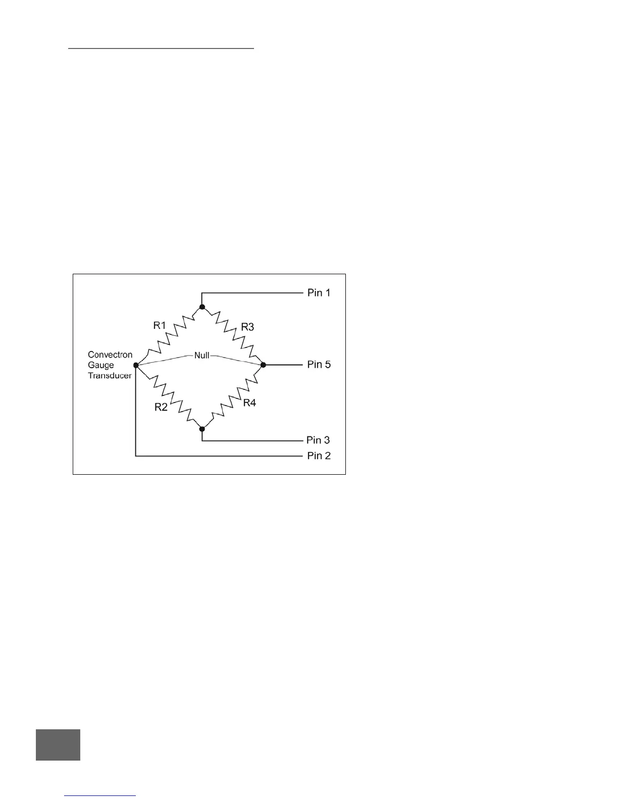
2.3 Convectron Gauge Tube Construction
The transducer is a convection enhanced Pirani gauge providing rapid response, six-decades of
pressure transduction, stable calibration, and good accuracy. The Pirani sensing element, R1 of the
schematic of Figure 2-3, is one leg of a Wheatstone Bridge. A temperature compensating network,
R2, forms the second leg of the bridge. The temperature sensitive component of this network is
mounted inside the gauge tube envelope with the sensor. All other resistors of the bridge are
mounted upon the exterior electrical feed through pins of the gauge tube. Pin 4 serves as an electrical
terminal for construction of the compensating network, R2, but no connection is made from the
controller.
All materials are compatible for ultra high vacuum service, corrosion resistance and bakeability to
150 °C. The gauge tube envelope is type 304 stainless steel. All metallic joints in the envelope are
welded. No solder is used within the envelope. The following materials are exposed to the vacuum:
Type 304 stainless steel, Carpenter Alloy 52, Kovar, Kapton
®
, gold-plated Tungsten (or Platinum) and
borosilicate glass.
Figure 2-3 Convectron Gauge Tube Schematic

 Loading...


