41
Series 275 Mini-Convectron Module with DeviceNet
Instruction Manual - 275563
Chapter 5
5 DeviceNet Operation
5.1 DeviceNet Digital Interface Setup
Use the following procedure to configure the DeviceNet digital interface on the vacuum system and
obtain a vacuum chamber pressure.
1. Turn OFF power to the Mini-Convectron Gauge Module.
2. Set the MAC ID switches on the Mini-Convectron Module to the correct address position (0 -
63) for the network on which it is installed.
3. Set the data rate switch to the appropriate baud rate setting. See Table 4-5.
4. Connect the DeviceNet network cable to the connector 275 Mini-Convectron Vacuum Gauge
Module.
5. Turn ON power to the DeviceNet connector on the Mini-Convectron Module.
6. See Table 5-1 and Table 5-2 to allocate a connection for the module to the network master. Set
the bit contents to 1 for a Polled connection, and 0 to enable Explicit Messages.
An explicit message connection must be allocated to allow a polled connection to be
allocated. They may be allocated simultaneously as shown in Table 5-1 and Table 5-2.
7. Allocate a connection for the Mini-Convectron Module to the network master as listed in Table
5-2.
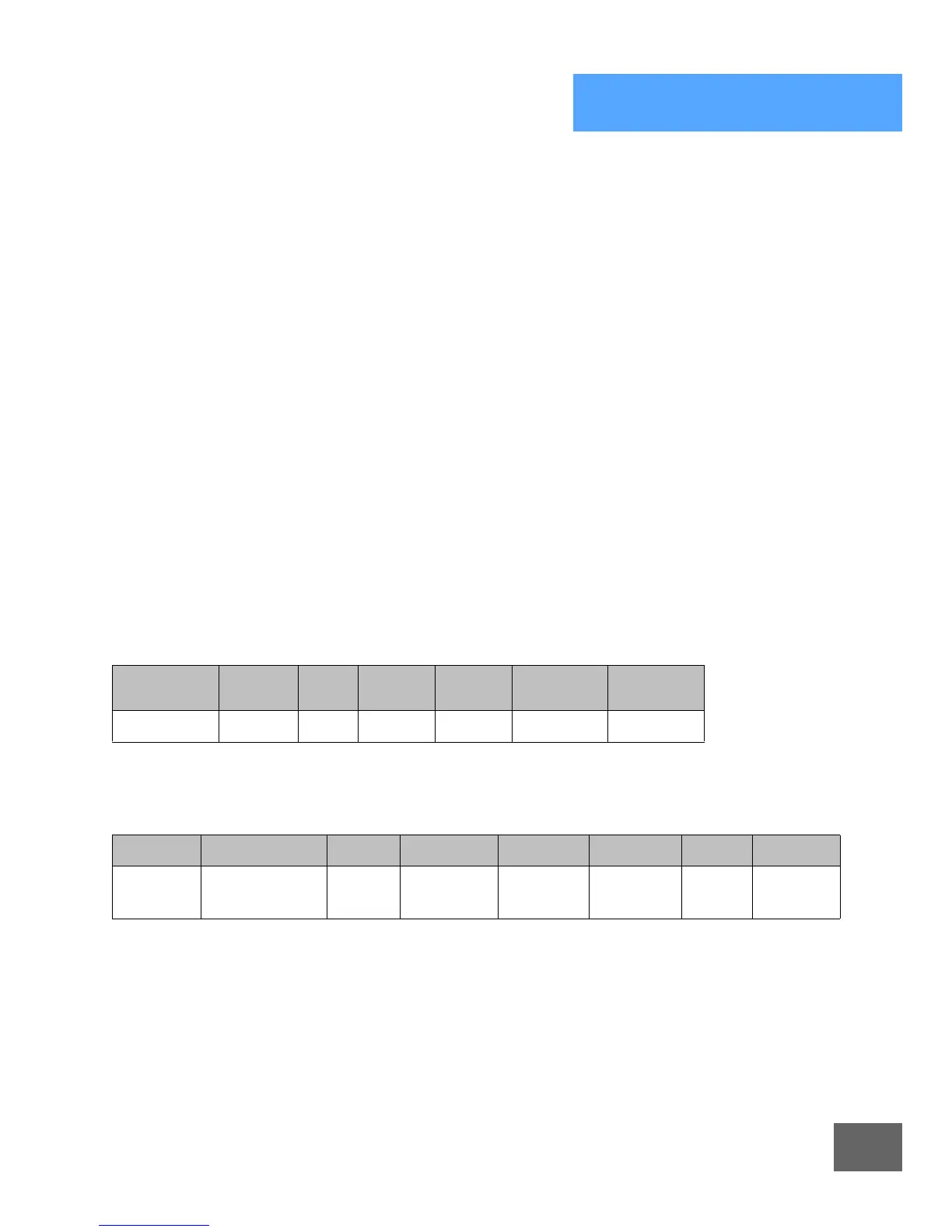
Table 5-1 Network Master Connection
Parameter Service Class Instance
Data
Typ e
Allocation
Choice
Master ID
Connection 4B
hex
3 1 STRUCT 3* 0 to 63
*Allocation Choice: 3 allocates a polled and explicit message connection.
Table 5-2 Allocation Choice Byte Contents
7* 6* 5* 4* 3* 2* 1 0
Reserved Acknowledge
Suppression
Cyclic Change
of State
Reserved Bit
Strobed
Polled Explicit
Message
* Not Supported, Value = 0 only.

 Loading...


