6 Service and Maintenance
61
Series 275 Mini-Convectron Module with DeviceNet
Instruction Manual - 275563
6. Carefully unplug the Convectron gauge from the spring-loaded sockets in the printed circuit
board.
6.4.4 Convectron Gauge Test Procedure
The small diameter sensor wire inside the gauge tube can be damaged by even small voltages. Do
not perform electrical continuity tests with instruments applying in excess of 0.1 volt when the
gauge is at vacuum, or 2 volts when at atmospheric pressure.
1. Remove the Convectron gauge tube as instructed above.
2. Use a low-voltage (maximum 0.1 V) ohmmeter to check resistance values across the pins on
the base of the gauge. Pin numbers are embossed on the base. Figure 6-4 illustrates the base of
the gauge.
The Convectron Gauge should show the resistances listed in Figure 6-4. Pin numbers are embossed
on the blue plastic pin feed-through of the gauge. Measure the resistance across the pins with the
gauge at atmospheric pressure, using an ohmmeter that will not apply more than 10 mA.
3. Replace the gauge tube if required. Install the gauge tube and reassemble the module.
4. Install the module onto the vacuum chamber and check it for proper operation.
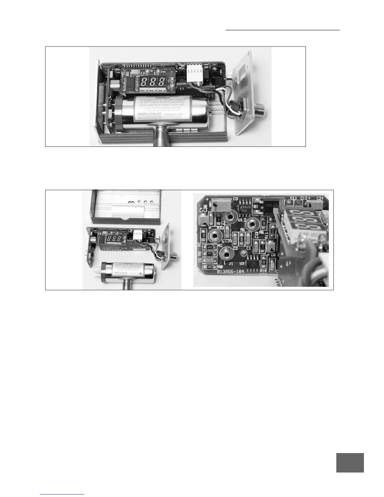
Figure 6-2 Mini-Convectron Module with Face Plate Removed
Figure 6-3 Convectron Gauge and PC Board Assembly

 Loading...


