6 Service and Maintenance
59
Series 275 Mini-Convectron Module with DeviceNet
Instruction Manual - 275563
6.4 Troubleshooting and Repair
6.4.1 Symptoms and Possible Causes
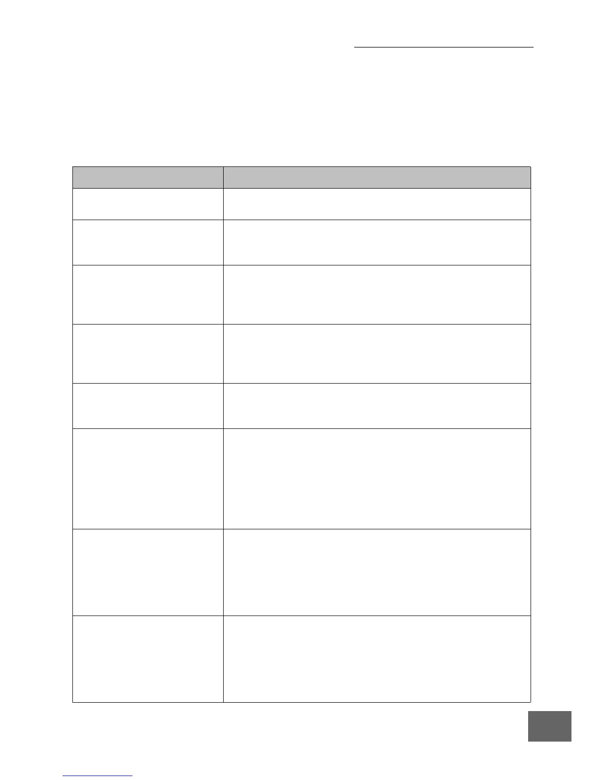
Table 6-1 General Symptoms/Possible Causes.
Symptom Possible Causes
The Mini-Convectron Module
will not power-up.
Check for +11 Vdc to +24 Vdc power across pins 2 and 3 of the
DeviceNet connector. See Section 3.4 in the Installation chapter.
The Bridge analog output
voltage reads less than +0.22
Vdc or greater than +10 Vdc.
Gauge tube failure. See Section 6.4.2 through Section 6.4.5 to check
the gauge tube.
Bridge amplifier failure. Replace the Module.
The Module does not respond to
DeviceNet communication from
a Master but the MOD Indicator
is illuminated solid green.
Address rotary switches set to incorrect address positions. Set the
address rotary switches to the correct address positions.
Incorrect baud rate. Set the baud rate switch in the correct position.
The MOD indicator does not
illuminate.
The DeviceNet power supply is disconnected, off, or inadequate for
the load. A switching supply may shut down from the current surge
upon power up. If a switching power supply is used, size the current
limit to two times working load.
The Module always reads
9.99e+09 via DeviceNet or the
MOD light turns red.
Fault condition indicated by reading response to status attribute. See
Section 5.1.5 for the DeviceNet command to check the status of the
Module, and to Section 5.4 for status bit definitions.
Pressure readout cannot be
calibrated using the specified
calibration commands.
The Convectron gauge tube is contaminated with material from the
vacuum chamber. Clean the gauge tube (see Section 6.4.5) or replace
the gauge tube.
If the gold plating on the sensor wire has been attacked by a gas such
as fluorine or mercury vapor, which has changed the emissivity or
resistance, cleaning the gauge tube will not solve the problem - the
gauge tube must be replaced.
The pressure readout from the
Mini-Convectron is vastly
different from that which is
observed by supporting gauges
on the vacuum system.
The gas composition in the vacuum chamber may not be what the
user believes it to be. Determine the actual type of gas in the chamber,
and calibrate the Mini-Convectron Module accordingly. See Section
3.6
in the Operation chapter.
U
nexpected gas sources can also be caused by the process within the
chamber or outgassing of the product in the process chamber.
Pressure reading grossly in error. The Module out of calibration.
Unknown gas type. Section 4.7.
The Module (gauge) is not mounted horizontally. See Section 3.3.
The Sensor is damaged (e.g., by reactive gas) or dirty. See Section
6.4.4 and Section 6.4.5.
Extremes of temperature or mechanical vibration.

 Loading...


