Instruction Manual #122162 41
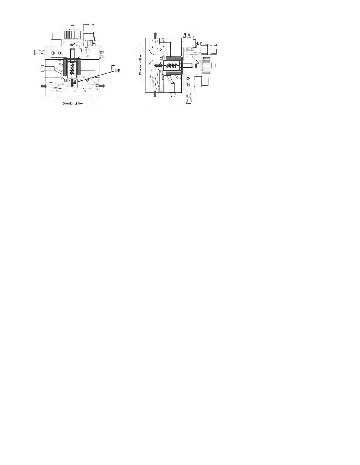
6.2.5 Affect of Forces on the Piston
The piston’s position forms a gap in the air flow path effectively creating an infinitely variable
resistor at the piston edge that responds mechanically to changes in exhaust pressure. For a
given process pressure and facility exhaust pressure, the piston will maintain a constant gap in
the air flow path. However, changes in the process pressure or facility exhaust pressure will
disrupt the force equilibrium. With the forces no longer in equilibrium the piston will move in the
direction of the resultant force until the forces are once again in equilibrium. This movement will
change the restriction (piston’s position) in the airflow path and its resulting resistance in order
to maintain a constant process pressure. Likewise, changes in process flow rate will disrupt the
force balance on the piston. This will cause the piston to move again in the direction of the
resultant force in order to maintain its equilibrium state at its set process pressure. The piston
will come to rest at a position where the sum of the forces are again balanced maintaining
constant process pressure.
If facility exhaust increases, the instant that facility exhaust begins to increase, the piston face is
exposed to a small increase in vacuum. This increase creates a small increase in the process
pressure force, which accelerates the piston in the direction of the resultant force. The piston will
then come to a new equilibrium position that again maintains the process pressure at the piston.
The differential pressure across the piston edge has changed to compensate for the increase in
facility exhaust. Likewise, for a decrease in facility exhaust the piston face will be exposed to a
small decrease in vacuum. This decrease creates a small decrease in the process pressure
force, which accelerates the piston in the direction of the resultant force.
6.3 Manual (“SINGLE”) Mode Sentry Controller with TIM-100/120
Manual operation of the SENTRY 1510 is accomplished by using the TIM-100/120 keypad. For
the TIM-120, access to the keypad and display requires the use of the TIM-200 program
module. Use the keypad to enter changes to the menu items provided by the TIM-100/120. Only
one menu entry is required for the Sentry 1510 (Manual Mode), pressure set point “PRES SP1”.
The remaining menu items are preset at the factory with settings that should satisfy the control
requirements of most installations. A list of the menu parameters and an explanation of the most
commonly used items is contained in “Serial Communication Programmer’s Guide for the
SENTRY TIM 100/120”. The default factory settings are listed in Appendix B.
6.3.1 Using the Keypad
The keypad contains four keys used to navigate and change the menu list and parameters.
Description of the keys is located in Section 1of this manual.