Instruction Manual #122162 26
5.5 TIM 100/120 Installation
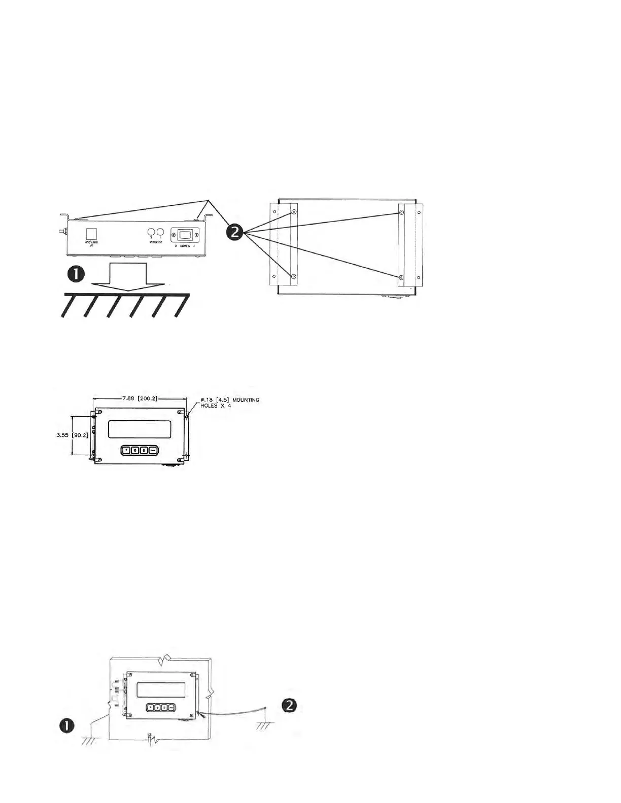
5.5.1 Attach the Mounting Brackets to the TIM 100/120
1. Carefully place the TIM 100/120 face down onto a flat surface.
2. Secure both brackets to the TIM 100/120 chassis using the included fasteners (2 each).
3. If the TIM 100/120 has been mounted to a facility structure or the process tool which is not
chassis grounded, connect a ground wire lead from the process tool chassis ground to one of the
TIM 100/120 mounting brackets as indicated below. Use an insulated wire with a minimum 16
AWG stranded wire. Refer to Appendix C for the recommended complete system grounding.
5.5.2 Mount the TIM 100/120 to the Tool
Having selected a location for the TIM 100/120, mount the TIM 100/120 to the support structure
using the holes located on the mounting brackets installed previously.
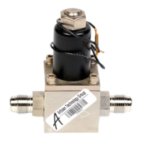
5.5.3 Ground the TIM 100/120
The TIM 100/120 should be chassis grounded to the process tool. Depending on the installed
location, a ground wire may be required.
1. If the TIM 100/120 is mounted on the process tool through metallic contact and the process
tool is chassis grounded, no ground lead is required.
2. If the TIM 100/120 has been mounted to a facility structure or the process tool which is not
chassis grounded, connect a ground wire lead from the process tool chassis ground to one
of the TIM 100/120 mounting brackets as indicated below. Use an insulated wire with a
minimum 16 AWG stranded wire. Refer to Appendix C for the recommended complete
system grounding.