Instruction Manual #122162 39
6. Operation
6.1 Introduction
The SENTRY 1510 pressure controller is designed to maintain a constant pressure in a sealed
process chamber, compensating for varying process gas flows and fluctuating house exhaust.
There are three essential elements that make up the SENTRY system: (1) the mechanical
piston based 1510, (2) the microprocessor based TIM 100/120 and (3) the CD-20 condenser for
wet processing. The SENTRY system has been designed to operate with minimal operator
involvement. In most cases, once the unit is installed, no manual adjustments or maintenance
is required.
6.2 Operational Theory
The SENTRY 1510 theory of operation can be explained in the four-diagram sequence below.
The piston is the single moving part that provides the continuous regulation of varying gas flows
and facility static exhaust. The stepper motor and electronics do not contribute to the regulation
of the process gas flows or the facility exhaust but instead provide a means of setting individual
set points and providing a continuous read-back signal of process exhaust pressure.
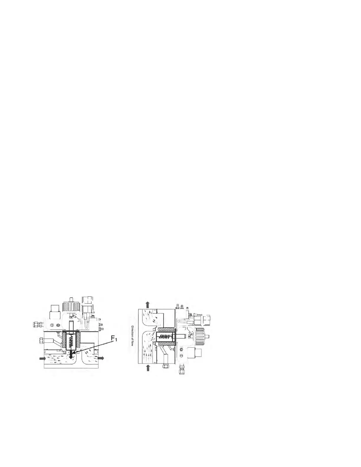
A cut-away diagram of the SENTRY 1510 is shown below to demonstrate the forces acting on
the piston. In the diagrams below, the arrow indicates the gas flow direction from the tool
exhaust entering the SENTRY 1510 and exiting to the facility exhaust. The SENTRY system
isolates the process exhaust from the facility exhaust fluctuations through the use of a force
balance acting on the piston. As noted in the installation section, the SENTRY 1510 can be
configured to operate in both a horizontal and vertical flow orientation. The force balance
providing the process exhaust pressure regulation is similar in both instances.
6.2.1 Force of Gravity
The first force (F
1
) acting on the piston is that of its own weight due to gravity. This force acts in
the downward direction. This force does not influence the controlling force balance system in the
vertical flow configuration because it acts perpendicular (normal) to the piston force balance.
With facility exhaust (P
HE
) at zero, there is no differential pressure acting on the piston surface.
Atmospheric pressure is acting on all surfaces with the net force on the piston equal to zero.
6.2.2 Force of Spring
The second force acting on the piston is that of the spring (F
kx
). The spring connects the piston
with the stepper motor. Notice that this connection is not a rigid link. Depending on the stepper
motor position the spring will exert a compressive or tensile force on the piston, resulting in an
effective weight relative to the exhaust stream. In the horizontal flow configuration, the spring
exerts a force in the vertical plane. Likewise, in the vertical flow configuration, the spring exerts