Instruction Manual #122162 28
5.7 SENTRY Cable Installation
• Cable drawings are provided in the drawings section at the end of this
manual.
• Both the CE and non-CE cable plugs have alignment keys that must be
aligned with the mating panel connector. When the cable plug is fully
inserted, lock it in place.
• Secure all cables with strain relief fasteners.
5.7.1 Connect the TIM 100/120 to the SENTRY 1000 Cable
The SENTRY system is manufactured in CE compliant (“CE”) and non-CE compliant (“non-CE”)
models. The CE compliant interface module is referred to as a TIM 100 (depicted in all
diagrams) or a TIM 120 (not shown). The non-CE modules were previously referred to as
SENTRY Supervisors (not shown). Most differences between the two models should be
transparent to the user. However, the two models do not share the same cable connector styles
and connector locations. The CE compliant model has DB connectors which are located on the
left panel while the non-CE compliant model maintains the original plastic circular connectors
which are located on the bottom panel.
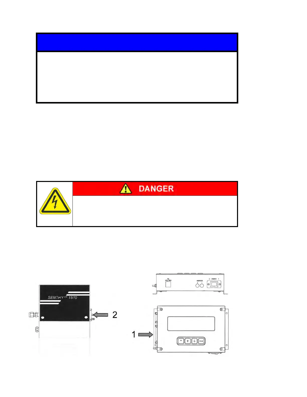
Electrical Shock
Turn OFF power to the TIM 100/120 before installing or
removing the SENTRY cabling.
1. Connect the 25-pin male DB (CE) connector labeled “P3” to the right hand connector on the
TIM 100/120 labeled “TO SENTRY CONTROLLER”.
2. Connect the 15-pin female DB (CE) connector labeled “P4” to the SENTRY 1510 controller.