Instruction Manual #122162 29
5.7.2 Connect the TIM 100/120 Power and/or Tool Interface
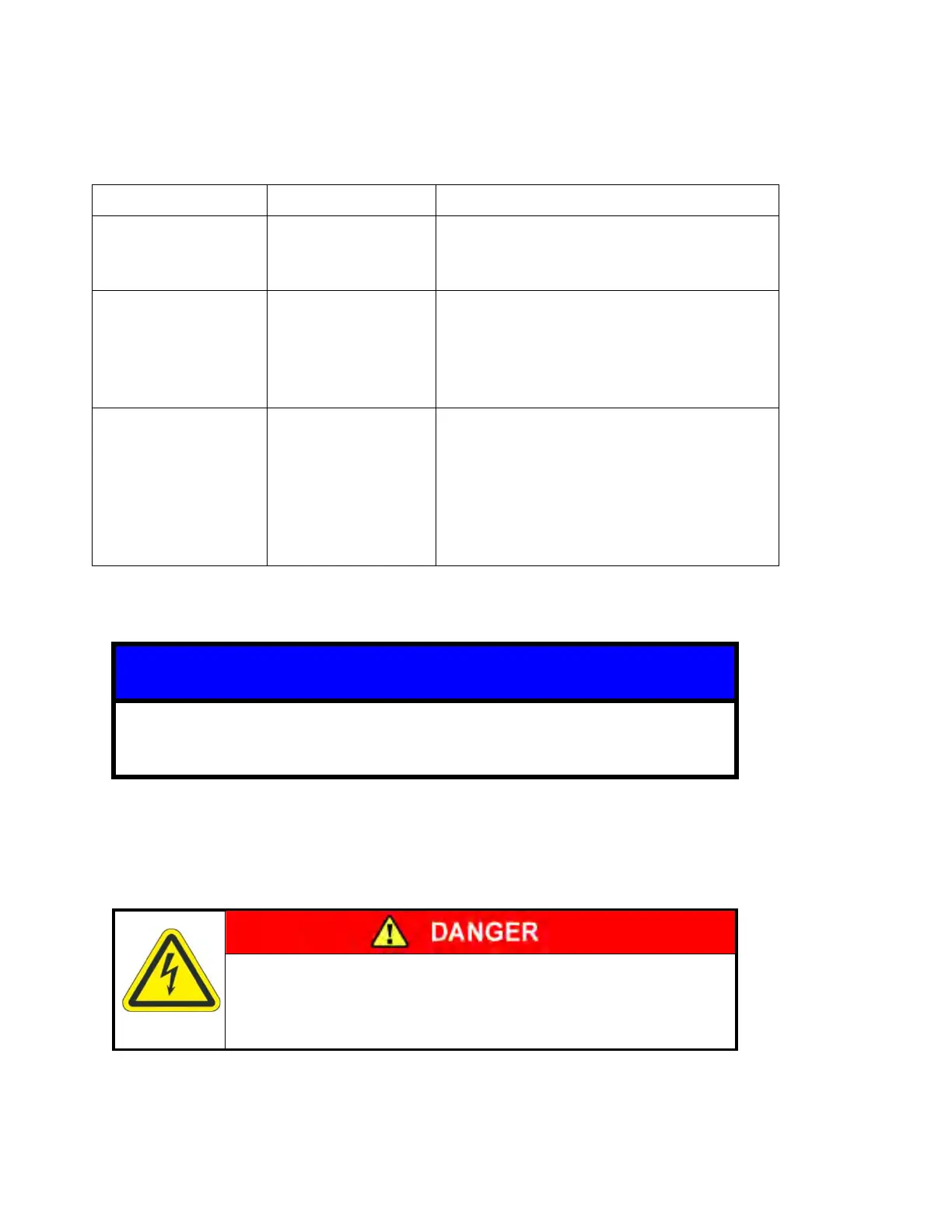
Depending on the control interface chosen, the system will both require a stand-alone power
supply or a tool power and interface cable. Refer to the table below for the appropriate cable
connection.
Stand-Alone
Power Supply.
TIM 100/120 changes are manually
entered on the TIM 100/120 key pad
(no tool interface).
Tool to TIM
100/120 Interface
Cable
Power is supplied on the same cable
as the analog communications. The
process tool supplies both power and
communication through this single
cable.
Stand-Alone
Power Supply
or
Tool to TIM
100/120 Interface
Cable
In addition to the serial communication
cable, one of the two power supply
cables is required. Power can be
supplied from either the stand-alone
power supply or from the tool using the
tool to SENTRY interface cable.
In case of over-current situations on AC mains, the SENTRY system relies
upon the tool for alternating current (AC) disconnect.
Electrical Shock
Turn OFF power to the TIM 100/200 before installing or
removing the SENTRY cabling.
Stand-Alone Power Supply:
1. Connect the 9-pin female DB (CE) or the 10-pin male circular (non-CE) connector to the left
hand connector on the TIM 100/120 labeled “POWER IN/ANALOG INTF”.
 Loading...


