Instruction Manual #122162 30
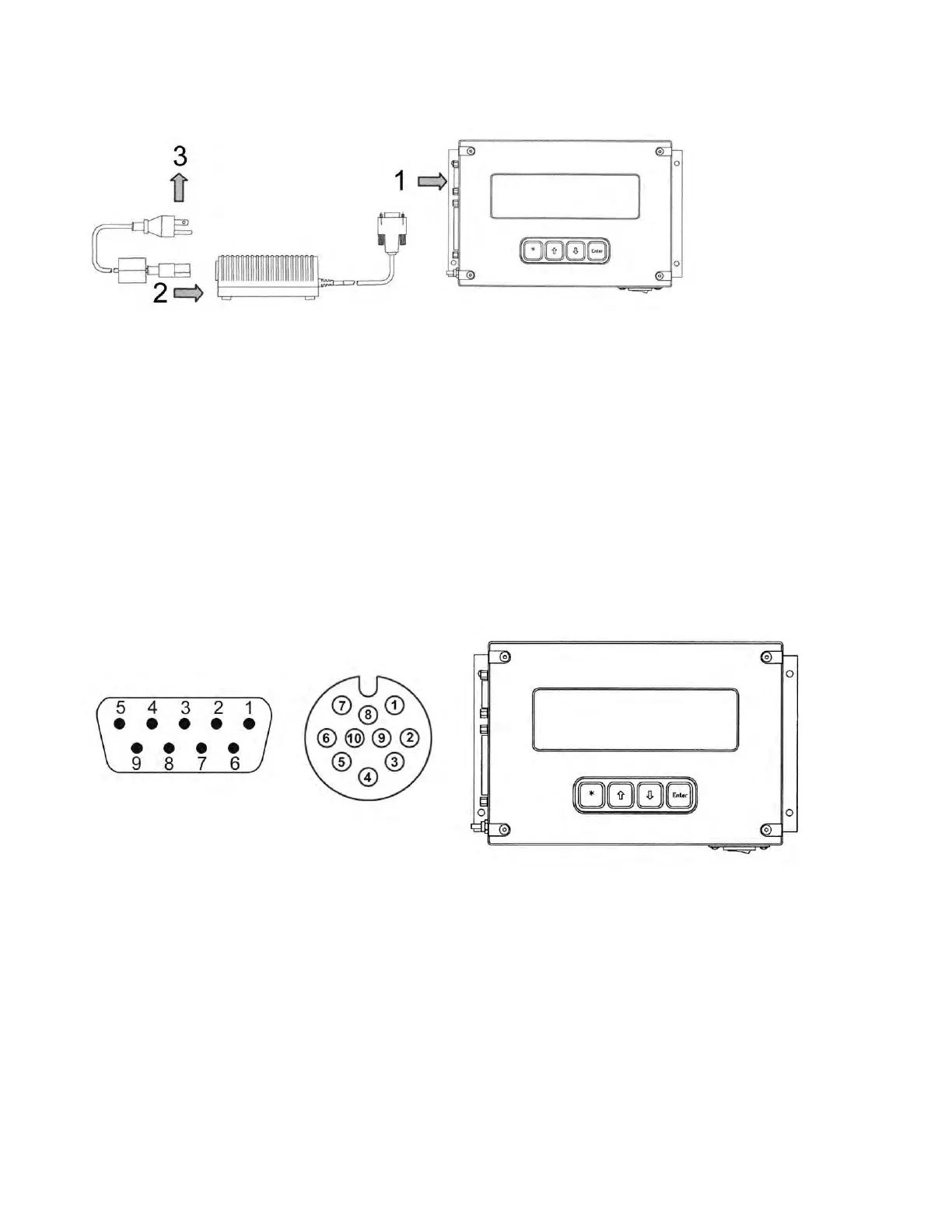
2. Connect the female plug of the power supply cable into the power supply box.
3. Connect the male plug or flying leads of the power supply cable to the appropriate electrical
supply.
Tool to TIM 100/120 Interface Cable:
1. Connect the interface cable end labeled “P1” to the tool. The connector style varies to
accommodate OEM tool connector styles.
2. Before connecting to the TIM 100/120, use a volt meter to verify that the proper power and
signal voltages are present. For pin assignments, refer to the appropriate cable drawing in
the drawings section at the end of this manual.
3. Verify that both power ground and analog ground are connected and that they are common
on the tool by performing a continuity check between the analog and power ground pins.
4. Connect the 9-pin female DB (CE) or the 10-pin male circular (non-CE) connector labeled
“P2” to the left hand connector on the TIM 100/120 labeled “POWER IN/ANALOG INTF”.
5.7.3 (Optional Configuration) Connect the Serial Communication Cable
The TIM 100/120 is capable of RS422/485 serial communications. The communications can be
with the process tool or with a host computer. Programming of the tool or host computer with the
proper protocol is required in order to use this option. Refer to the “TIM 100/120 Operations and
Serial Communications Guide” for further details. A serial communication cable must be
installed to use the serial communication port.