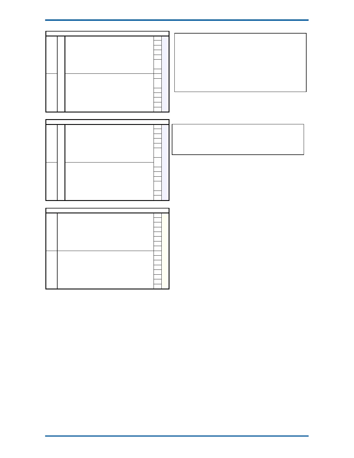
EMC INDUSTRIAL GROUP LTD I/O Function Table
MW93A_IM_ALL_SV6.09f_en 54/59
Output Functions
112 weight fault 0
113 1
114 flowrate fault 2
115 not filling or discharging 3
116 low flow fault 4
117 5
118 error limit fault 6
119 7
120 8 Ϯ
121 user fault 1 9 Ϯ
122 user fault 2 10 Ϯ
123 user fault 3 11
124 12
125 Comms fault 13
126 P-Module not compatible 14
127
output function
no P-Module fitted 15
Faults
Output Functions
144 IN1aux 0
145 IN2aux 1
146 IN3aux 2
147 IN4aux 3
148 IN5aux 4
149 IN6aux 5
150 IN7aux 6
151 IN8aux 7
152 OUT1aux 8
153 OUT2aux 9
154 OUT3aux 10
155 OUT4aux 11
156 OUT5aux 12
157 OUT6aux 13
158 OUT7aux 14
159
output function
OUT8aux 15
IOxAux
Input Functions (level sensitive Π or edge sensitive )
160 0
161 1
162 2
163 3
164 4
165 5
166 6
167 7
168 8
169 9
170 10
171 11
172 12
173 13
174 14
175 15
Control4
The Faults register holds the fault status of the unit.
Faults are conditions that are either present or not. The source of the fault must be
removed to clear the fault.
The “fault bit” (61) is on when any fault condition exists.
User faults can be created and cleared by setting and resetting bits.
Alarms
Alarm events are created by a new fault or other alarm sources in the controller.
When any alarm event occurs, the “alarm” (62) and “alarm alert” (63) bits are set.
When alarms are acknowledged (45), the “alarm alert” is reset.
The “alarm” bit will also be reset by an acknowledge if there are no faults present.
This register hold the state of inputs IN1aux to IN8aux and outputs OUT1aux to
OUT8aux.
The output states are set using the factory default OUT1 to OUT8 functions.