Appendix C: Operator Performance Check
Reflected Rise Time Check (10-90%)
Reflected Rise Time Check (10-90%)
To measure reflected rise time of an individual CT100 it is important that nanoseconds and
millirho are visible on the unit screen. The two units may be enabled within the Display submenu.
To determine the CT100 rise time:
1) Apply the shorting cap to the CT100 front panel cable connector.
2) Ensure that the RRC method is set to the 1502C method.
3) Adjust the on-screen trace so that the internal cable is shown completely. Figure 24 displays
the internal cable on a CT100HF unit.
4) Position the trace so that the leading edge of the internal cable (the left side of the trace) is
centered on the screen.
5) Adjust the horizontal scale so that the trace is positioned diagonally across the screen, and
adjust the vertical scale so that the left side of the trace runs along the base of the screen and
the right side of the trace runs along the top of the screen. The difference between the two
sides is considered 100% of the rise time and should be close to 1000mρ.
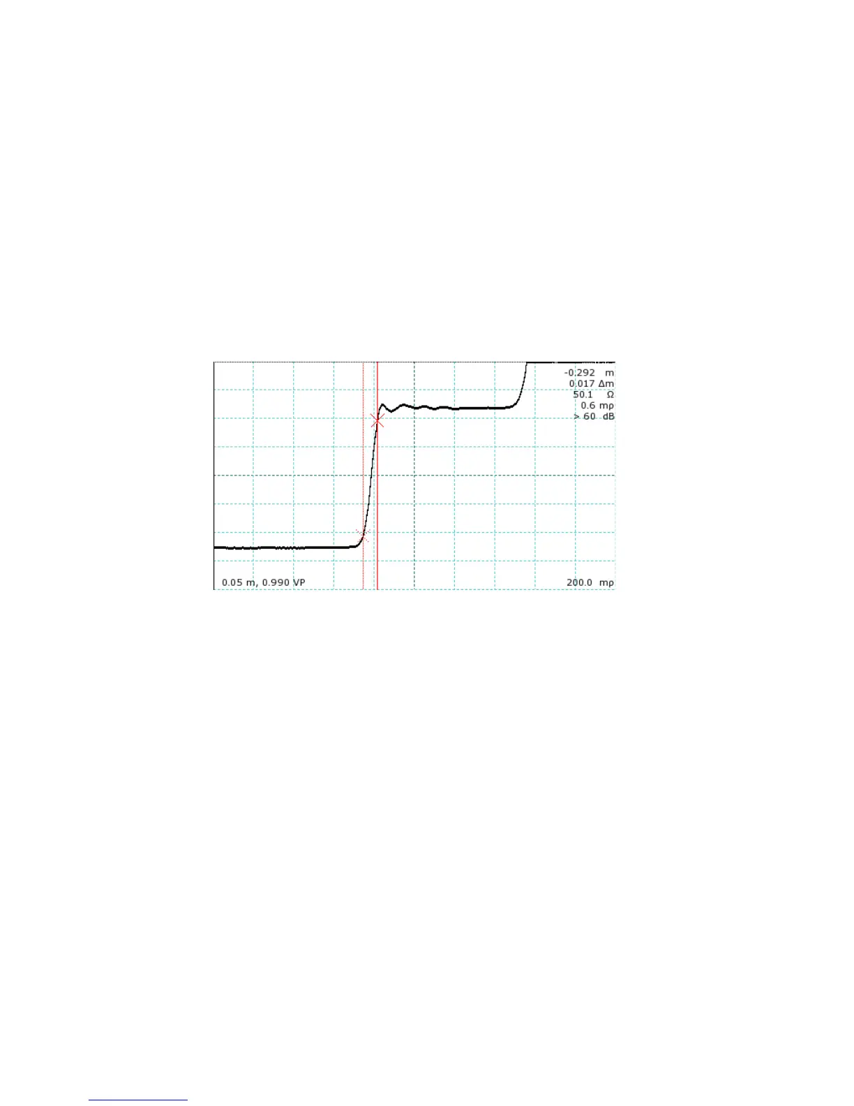
6) To find the 10-90% rise time, position one cursor at -900mρ and the second cursor at -100mρ.
Figure 25 shows a trace correctly positioned for rise time measurement on a CT100HF screen,
with the cursors placed at the 10% and 90% points.
72 Mohr CT100 / CT100HF Operator's Manual
Figure 24: Trace preparation for rise time measurement. The
internal cable trace is fully displayed on-screen, and the rising edge
is centered.