Appendix D: Calibration Procedures
4) Center the cursor in the middle of the screen using the position knobs.
5) Expand the scale to 0.0100 ft/div and 1.0 mρ/div.
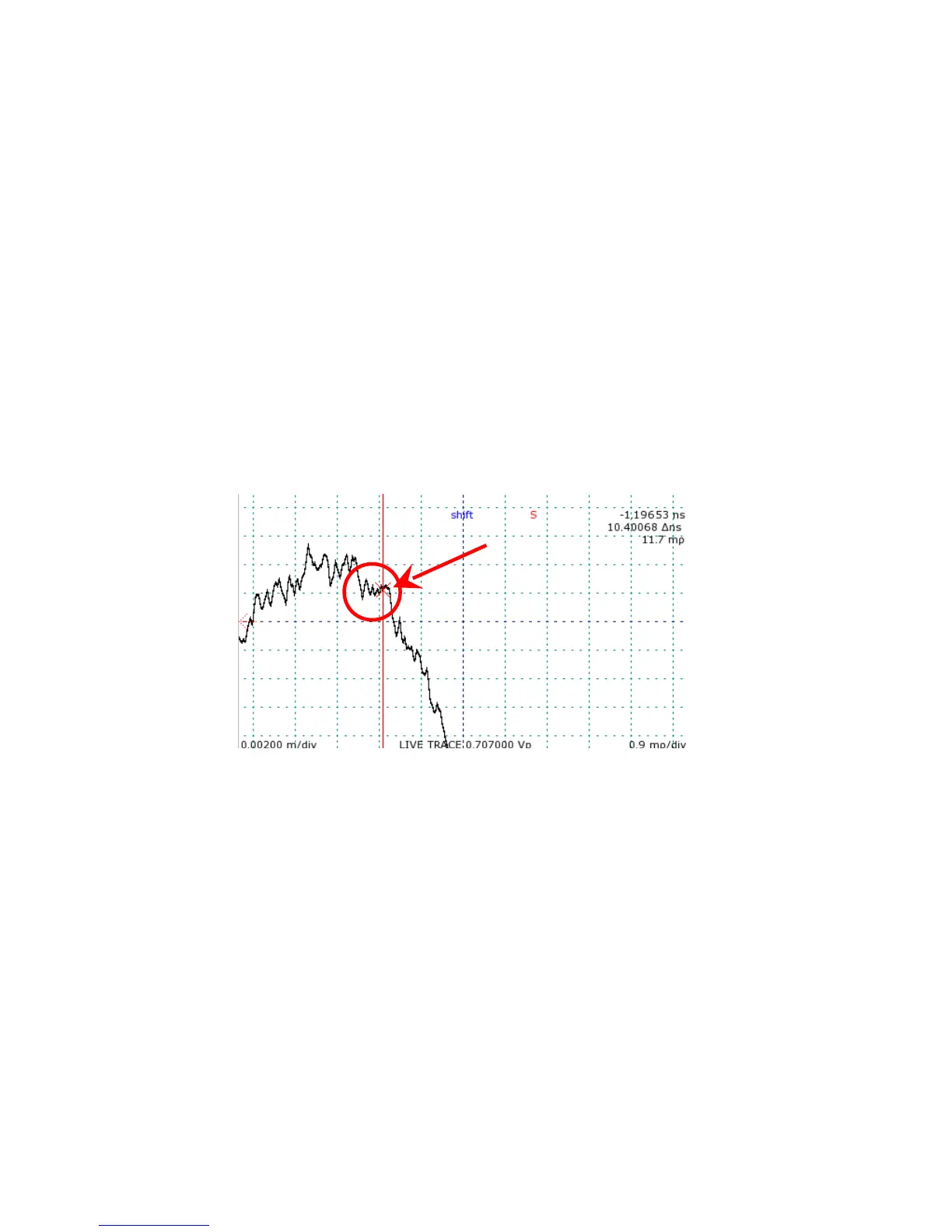
6) Locate the small break in slope on the falling edge shortly after the final peak on the live
internal cable trace.
It may be necessary to adjust the scale further to find the obvious break point signifying the
cable end. Refer to Figure 33 for an example.
7) Position one cursor at the end of the break point.
8) Enter the Calibration submenu.
9) Press Horizontal (Button 5) to set horizontal calibration.
10) Press Button 4 for OK to continue.
Horizontal calibration must be set for each pulse setting. Change to the next pulse setting and
repeat steps 1 through 9. Repeat again for the final pulse setting.
After horizontal calibration, measure a known length of cable to verify accurate start point
positioning.
88 Mohr CT100 / CT100HF Operator's Manual
Figure 33: Identification of cable start position. The circled portion
of the trace is the point signifying the front panel cable connector.
The active cursor should be moved to the flat section of the trace
pointed to by the arrow.