Appendix D: Calibration Procedures
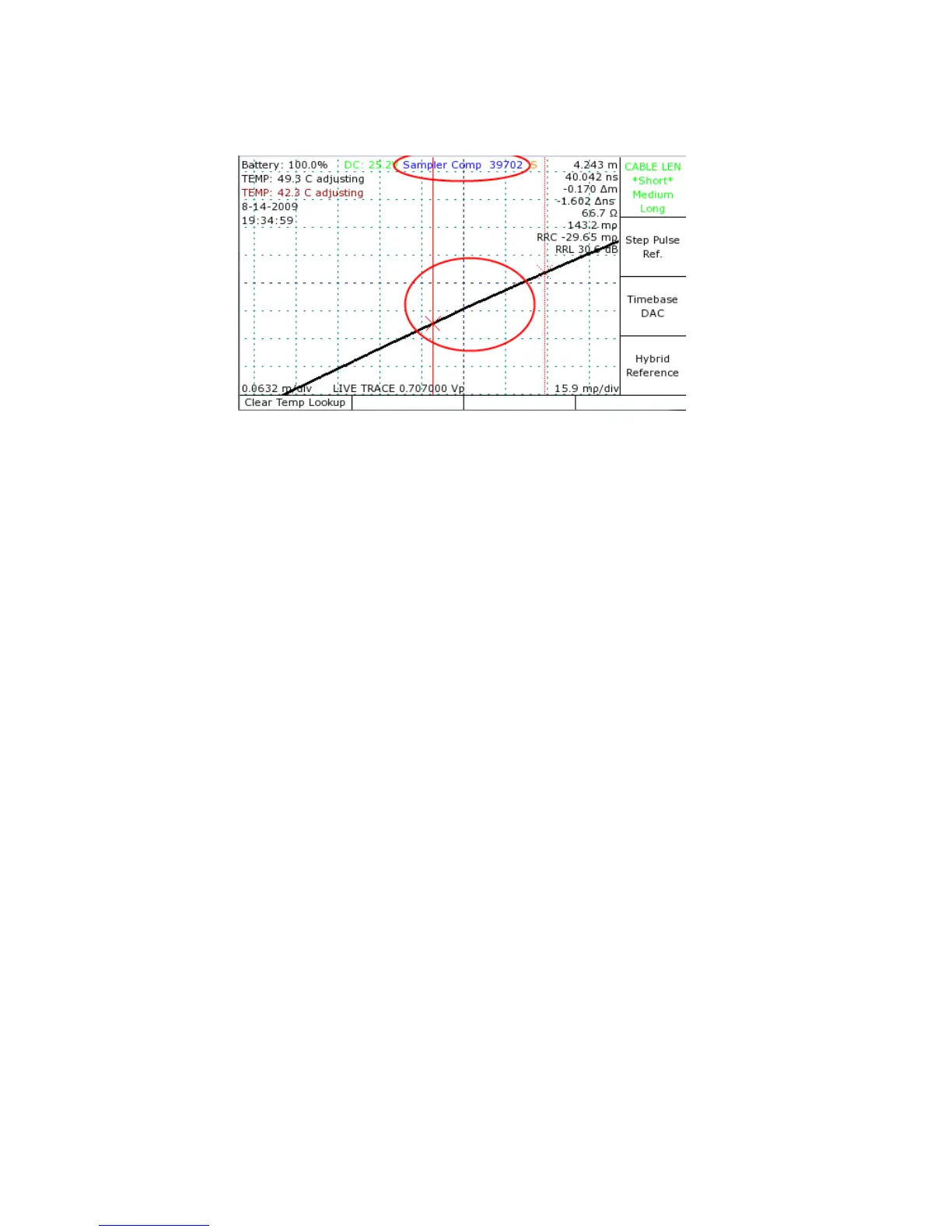
9) Rotate the M-FUNCTION knob until the live trace appears linear as in Figure 27.
10)Repeat steps 1 through 9 for short, medium, and long maximum cable lengths.
Manually verify resistive load calibration
The following text discusses the manual resistive load calibration procedure, which you can
use at any time to check and/or manually adjust the vertical calibration of the instrument for
maximum precision of vertical measurements. From the Main menu, select Calibration, press
OK when the warning appears, and then select Manual Calibration.
1) Remove all cables from the front panel cable connector.
2) Adjust the CT100 scale to 0.5 ft/div (0.15 m/div) and 500 mρ/div.
3) Place the cursor as shown in Figure 28 on the rising edge of the internal cable segment.
4) Center the cursor in the middle of the screen using the position knobs.
5) Expand the scale to 0.070 ft/div and 40 mρ/div.
6) Push the Hybrid Comp button to start the manual resistive load calibration. The automatic
calibration option is discussed elsewhere in this manual. At this point the words “Hybrid
Comp” appear at the top of the screen with a 5 digit number as shown in Figure 28. This
trace is typical of a CT100 with the self-grounding BNC test port and/or with a shorting
terminator applied. The CT100HF does not have the shorting BNC and will show an open
condition at the end of the trace if a shorting terminator is not applied.
84 Mohr CT100 / CT100HF Operator's Manual
Figure 27: Example of a correctly set capacitive calibration. The
circled area is the 50 rollover. Compare against Figure 26 where
manual adjustment is necessary.