STAR™ 3000 / eNode3000 User Manual
www.mojix.com
(877) 886-6549
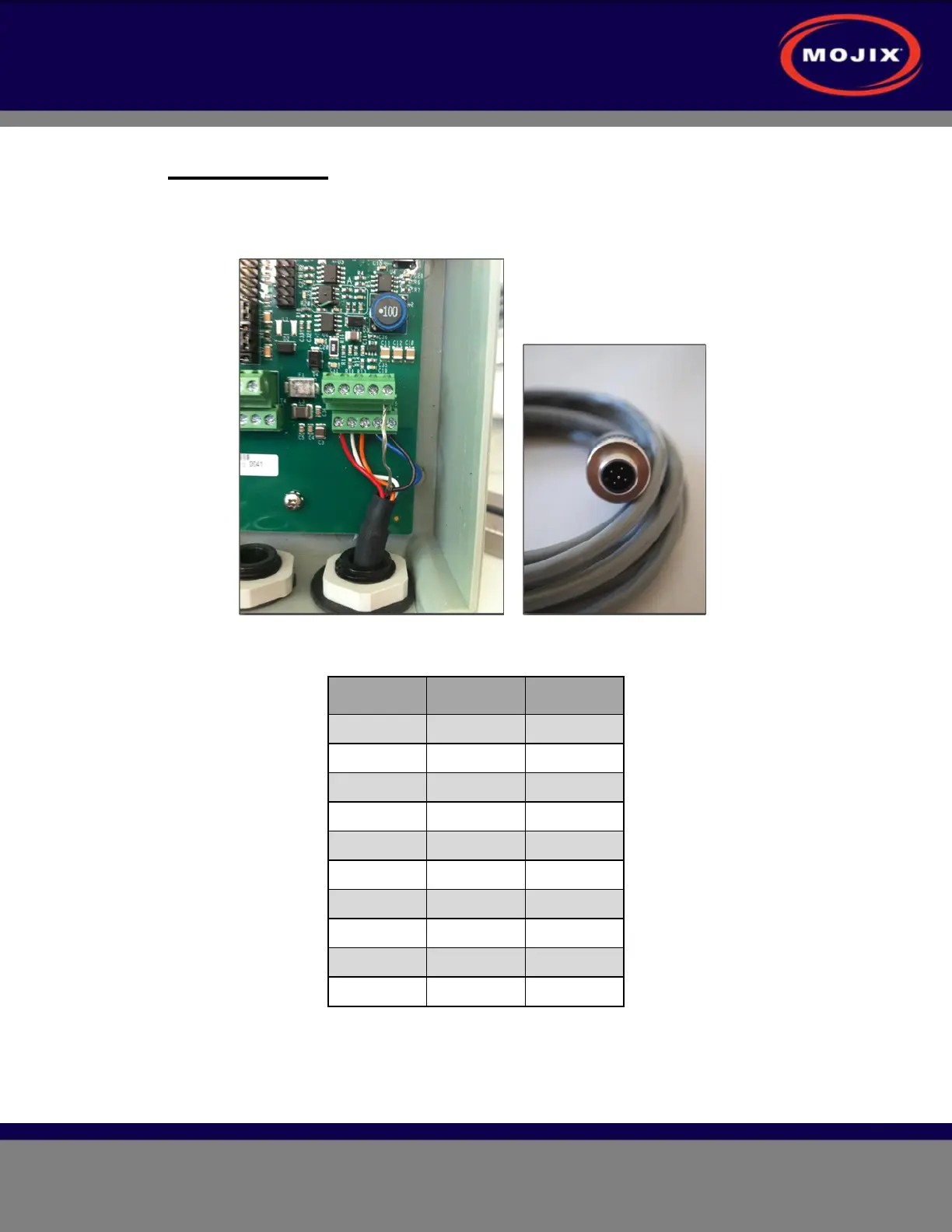
8.2 GPIO Cabling
The GPIO unit comes with the input cable pre-installed; however, in the case where GPIO
boxes need to be daisy-chained together, the following figure and table provide wiring and
pinout details for the input terminal block.
Figure 20: GPIO Input Terminal Wiring
Wire Color Signal
1 Red 24V
2 White RS-485 A
3 Orange RS-485 B
4 Blue + 3V
5 Black GND
6
7
8
9
10 Shield GND
Table 8: GPIO Input Terminal Block
For directions on how to connect sensors and actuators to the GPIO unit, please refer to the
GPIO User Guide which is provided separately.