SECTION TWO – WIRING AND INSTALLATION
DS2000 USER’S MANUAL (rev.C)
2.9
2.6 RECOVERY CIRCUIT
Standard recovery resistors are in the following table (see Section 5 for additional
informations) :
Dynamic braking unit
DS2000 Standard recovery resistor for 400/460 V
ac
mains voltage
Model Resistor and power Max Current Max Duty Cycle
3/9
4/12
75Ω/100W (ext.) 10A 1.3%
6/15
8/22
51Ω/200W (ext.) 14.7A 1.8%
14/42 33Ω/250W (ext.) 22.7A 1.5%
20/45
25/70
30/90
12Ω/370W (ext.) 62.5A 0.8%
50/140
60/180
10Ω/750W (ext.) 75.0A 1.3%
100/300 3.9Ω/1000W (ext.) 192.3A 0.7%
3/9
4/12
82Ω/150W (int.) 9.1A 1.0%
6/15 56Ω/150W (int.) 13.4A 0.7%
Tab. 2.3 – Recovery resistor data
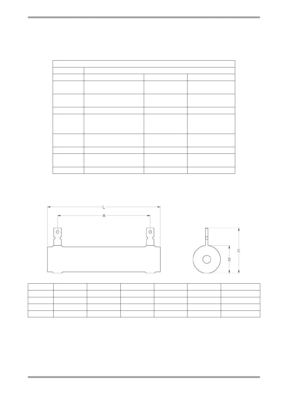
Dimensions declared by the supplier are in the following table:
Model 75Ω/100W 51Ω/200W 33Ω/250W 12Ω/370W 10Ω/750W 3.9Ω/1000W
L [mm] 165 ± 2 215 ± 2.5 265 ± 3 265 ± 3 300 ± 5 400 ± 5
A [mm] 150 ± 2 200 ± 2.5 250 ± 3 241 ± 3 270 ± 5 370 ± 5
G [mm] 36 ± 2 46 ± 2 46 ± 2 53 ± 2 88 ± 2 88 ± 2
D [mm] 20.5 ± 1 30.5 ± 1 30.5 ± 1 39 ± 2 76 ± 2 76 ± 2
Tab. 2.4 – Mechanical data of recovery resistor