SECTION TWO – WIRING AND INSTALLATION
DS2000 USER’S MANUAL (rev.C)
2.20
• J9 Terminal block
- Pos. 1,2 Phoenix – HDFK4 : Wire stripping: 9 mm. Tightening torque: 0.7 Nm.
- Pos. 3,4 Phoenix – HDFK25 : Wire stripping: 19 mm. Tightening torque: 4 Nm.
- Pos. 5 to 14 Phoenix – HDFK50 : Wire stripping: 24 mm. Tightening torque: 8 Nm.
Pos. Name Function
1 ■ 24V fans
2 0V fans
Voltage inputs 24V
dc
fans ±10%, 2A
3 RR External recovery resistor
4 RR (+AT) External recovery resistor and +HV of DC BUS
5 GND Housing ground
6 U1 Phase "L1", three-phase voltage input 230/460V
ac
±10%
7 V1 Phase "L2", three-phase voltage input 230/460V
ac
±10%
8 W1 Phase "L3", three-phase voltage input 230/460V
ac
±10%
9 GND Motor ground
10 U2 Phase "U2", motor three-phase output
11 V2 Phase "V2", motor three-phase output
12 W2 Phase "W2", motor three-phase output
13 +AT
14 -AT
DC BUS (see Application Engineer for details)
Tab. 2.15E – J9 power connector, size E
2.11.1.4 POWER WIRING NOTES
It is recommended to use motor phases wiring with low capacitance (max 500 pF/m).
CAUTION: do not parallel power connection cables to achieve requested section: this will
increase the capacitance value at levels that may irreversibly damage the drive. If the
value of capacitance of motor and cables, seen from drive output, exceeds 30 nF it is
necessary to verify with Moog technicians the need of an adequate choke in series.
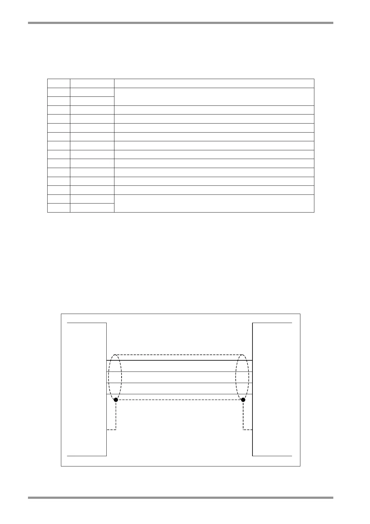
U
W
V
GND
U2
V2
W2
GND
DS2000 MOTOR
Grounding of shield
via connector clamp
(or RF connection to
metallic PG gland in
case of terminal board)
Grounding of shield
via connector clamp
Fig. 2.9 – Three phase motor supply wiring