SECTION TWO – WIRING AND INSTALLATION
DS2000 USER’S MANUAL (rev.C)
2.23
2.11.2.2 INPUT REFERENCES CONNECTOR (J2A)
Analog references (speed and current limit references) are available on the J2A
connector. The conductors are fastened by insertion, opening the connector using a
screwdriver.
• Mating connector: insertion type, 4 poles (Moog code AK4714).
Pos. Name Function
1 ■
V
Ref
+
Differential, non-inverted input of speed or torque reference signal (0÷
±10V, corresponding to 0÷ ±Max input reference). The end of scale is
adjustable via software from ±3.2 to ±10V in steps of 0.1V
2
V
Ref
-
Differential, inverted input of speed or torque reference signal
3
I
limit
+
Differential, non-inverted input of analog current limit (0÷ ±10V,
corresponding to 0÷ 100%Max set current). The end of scale is adjust-able
via software from ±3.2 to ±10V in steps of 0.1V
4
I
limit
-
Differential, inverted input of analog current limit
Tab. 2.17 – J2A input references connector
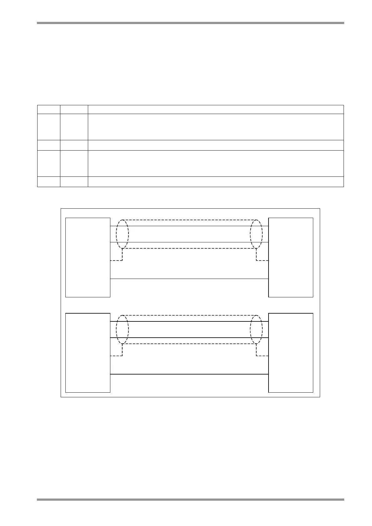
OUT+
Housing
GND
1_J2A_V
Ref
+
2_J2B_0V
CNC-PLC
OUT-
Housing
2_J2A_V
Ref
-
DS2000
DIFFERENTIAL SIGNALS
CNC-PLC
OUT+
GND
GND_0V
HousingHousing
DS2000
1_J2A_V
Ref
+
2_J2A_V
Ref
-
2_J2B_0V
SINGLE ENDED SIGNALS
NOTE: J2A and J2B are two different (separate) connectors.
NOTE: shields of cables must be 360° clamped to the cabinet wall
Fig. 2.11 – Example of connections