SECTION TWO – WIRING AND INSTALLATION
DS2000 USER’S MANUAL (rev.C)
2.24
2.11.2.3 DRIVE ENABLE CONNECTOR (J2B)
Drive enable, Drive OK signals, Tacho out, Analog out, and Reference enable are
available on the J2B connector. The conductors are fastened by insertion, opening the
connector using a screwdriver.
• Mating connector: insertion type, 12 pin (Moog code AK4722).
Pos. Name Function
1 ■ +15V OUT +15V
dc
output, max 100 mA
2 0V Logic Zero
3 ANL OUT Configurable output (see Analog out configuration)
4 TCH OUT
Tachometric signal output
(0 ÷ ±10V, corresponding to 0 ÷ ± Max speed rpm). The end of scale
is adjustable via software from ±5 to ±10V in steps of 0.1V
5 RESTART+
6 RESTART-
Opto-insulated Reset input (15 ÷24 V
dc
/12mA)
By means of a > 20 ms duration pulse the re-initialization of the
digital control card and the protections reset are carried out
7 DRV EN+
8 DRV EN-
Opto-insulated Drive Enable input (15 ÷ 24 V
dc
/12mA)
When signal is missing the drive does not supply current
9 REF EN+
10 REF EN-
Opto-insulated Reference Enable input (15 ÷ 24 V
dc
/12mA)
When signal is missing the motor is in standstill position, at zero
speed if in speed control mode, it has zero torque if in torque control
mode. This input can be used for emergency braking
11 DRV OK
12 DRV OK
Drive OK outputs. Contact closed (24V
dc
relays, max 100 mA)
indicates that Drive is OK.
It is recommended to logically connect the DRIVE OK isolated output
presence to the power contactor, so that the power supply is disabled
in case of fault
Tab. 2.18 – J2B drive enable connector
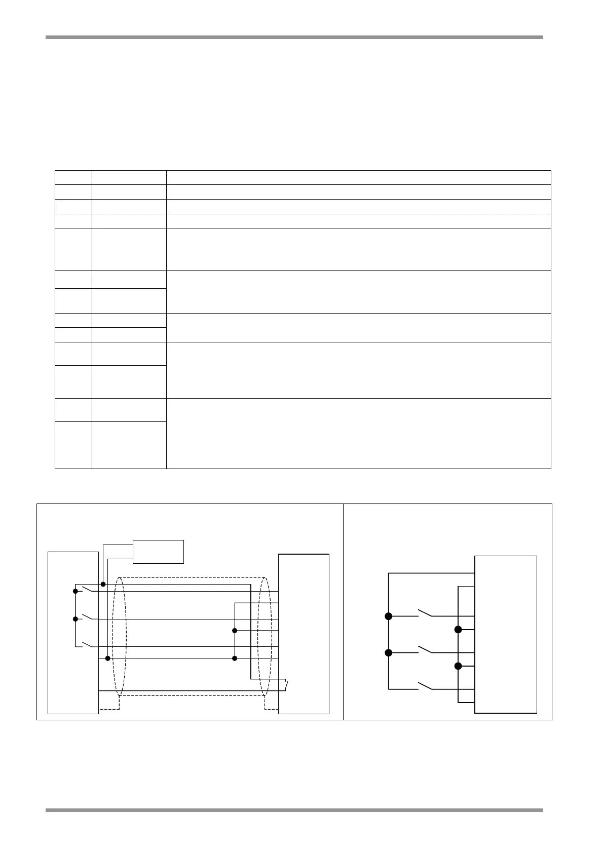
CNC-PLC
DS2000
DRIVE O
REF. EN.+
REF. EN.-
DRV OK
DRV OK
RST.+
RST.-
DRV. EN.+
DRV. EN.-
24V POWER
SUPPLY
+24V
0
WITH EXTERNAL 24V
dc
POWER SUPPLY
+15V
DRV. EN.+
DRV. EN.-
RST.-
RST.+
0V
REF. EN.-
REF. EN.+
DS2000
WITH INTERNAL ALIMENTATION
Fig. 2.12 – Example of wiring