SECTION TWO – WIRING AND INSTALLATION
DS2000 USER’S MANUAL (rev.C)
2.26
2.11.2.5 ENCODER INPUT CONNECTOR (J4)
NOTES: The motor control encoder is formed by two sections.
• The first one (UVW signals) only generates signals used by the drive to power the
motor phases; this section is defined by the number of motor poles.
• The second one (ABC signals) generates reference signals also available for motion
control through external CNC; the number of pulses in this section is defined according
to final the Customer needs as well as to the application requirements.
All the motor encoder channels and the PTC/NTC for the motor temperature control must
be connected to J4 connector located on the bottom side of the drive. The same
incremental encoder signals are available as output on J2C connector.
The mating encoder connector at drive side is a Sub-D 15 pos., to be soldered (Moog
code AK5221). It is recommended to use a low capacitance, multipolar cable with 22
AWG (0,30 mm2) or 20 AWG (0,50 mm2) conductors, shielded (with 85% min. coverage).
Cable length should not exceed 40 m. It is recommended that the cable and the power
connection cable must be separated through the use of independent duct and by a
distance of 30 cm. It is also recommended not to make intermediate connections on the
encoder cable.
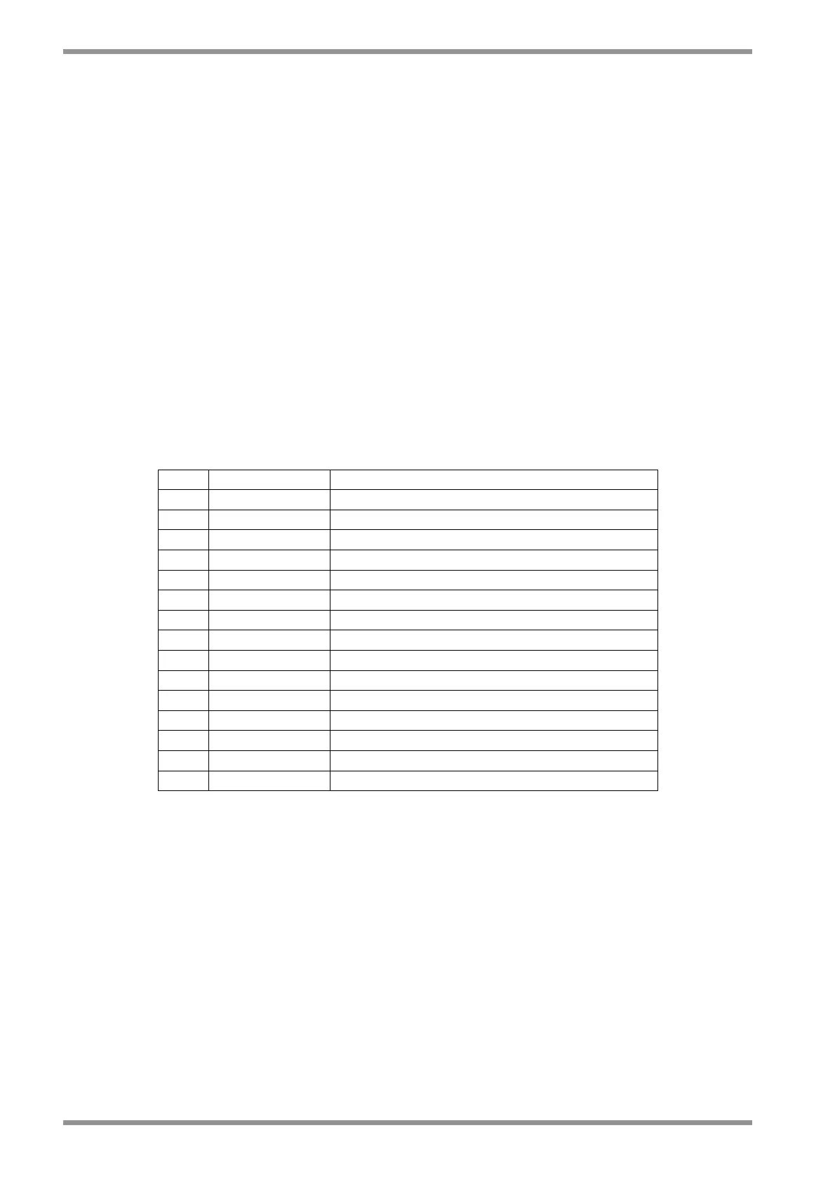
Pos. Name Function
1 ■ +5V +5 V
dc
(max 100 mA) output
2 0V Encoder ground and motor PTC/NTC
3 W- Switching signal: W phase denied
4 W+ Switching signal: W phase
5 V+ Switching signal: V phase
6 V- Switching signal: V phase denied
7 A+ A Channel
8 A- A Channel denied
9 C+ C Channel
10 C- C Channel denied
11 U+ Switching signal: U phase
12 U- Switching signal: U phase denied
13 B- B Channel denied
14 B+ B Channel
15 PTC_MOTOR Motor PTC/NTC
Tab. 2.20 – J4 encoder input connector