SECTION TWO – WIRING AND INSTALLATION
DS2000 USER’S MANUAL (rev.C)
2.33
2.11.3.2
G MOTOR CONNECTION
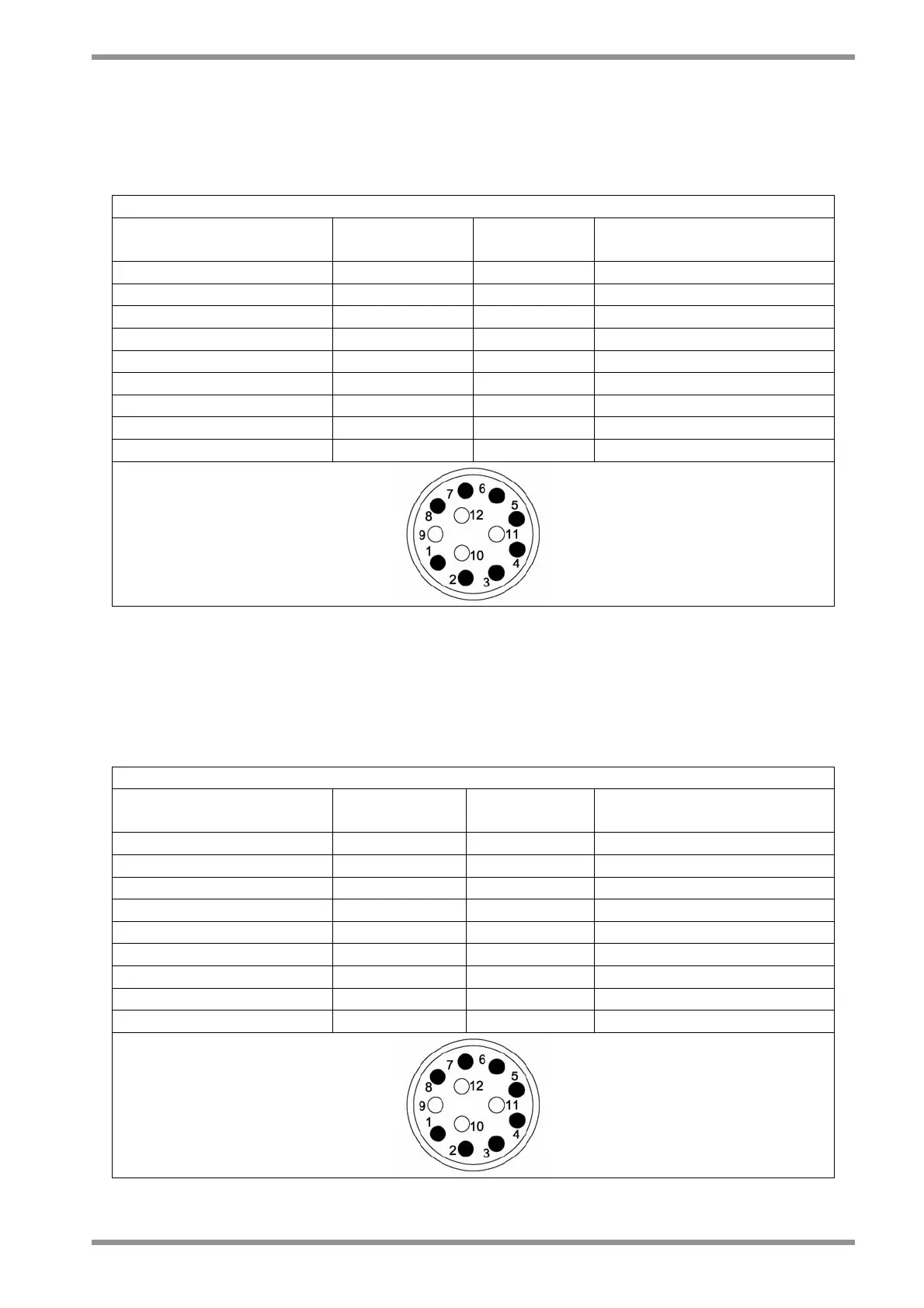
To standardize the resolver connection it is recommended for the new applications to use
the new resolver connection scheme of Tab.2.25A.
RESOLVER CONNECTION
Drive resolver connector
Pin No.
Name Pin name
on G motor
Motor resolver connector
Pin No.
1 ■ COS+ S2 3
2 COS- S4 4
3 SHIELD
4 SEN+ S1 1
5 SEN- S3 2
6 PTC_MOTOR THERM 1 5
7 10kHz- R2 8
8 PTC_MOTOR THERM 2 6
9 10kHz+ R1 7
Tab.2.25A – New resolver connection scheme
The old resolver connection scheme shown in the previous revisions of this Manual and
reprinted in Tab. 2.25B is still valid.
CAUTION: It is recommended not to change the old connections in case of retrofitting
motors or drives.
RESOLVER CONNECTION
Drive resolver connector
Pin No.
Name Pin Name on
G motor
Motor resolver connector
Pin No.
1 ■ COS+ S4 4
2 COS- S2 3
3 SHIELD
4 SEN+ S3 2
5 SEN- S1 1
6 PTC_MOTOR THERM 1 5
7 10kHz- R2 8
8 PTC_MOTOR THERM 2 6
9 10kHz+ R1 7
Tab.2.25B – Old resolver connection scheme