SECTION TWO – WIRING AND INSTALLATION
DS2000 USER’S MANUAL (rev.C)
2.34
The ground (pin 3, drive side) has to be connected to the motor connector housing.
Several motor G have as standard a NTC for thermal feedback, the DS2000 can manage
PTC sensor or NTC sensor without any hardware change (see Section 6 for additional
data).
The resolver is looked mechanically: the customer has to perform the AUTOPHASING
with the drive utilities, checking that the value for the APHAPOS parameter is
–209 (±5Units) for 8 poles motor with 2 poles resolver or 45 (±5Units) for 12 poles motor
with 2 poles resolver (see Section 6 for additional informations).
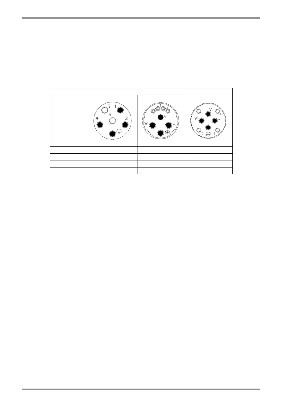
MOTOR POWER CONNECTOR
DS2000
GND GND GND GND
U 2 U U
V 4 V V
W 1 W W
Tab. 2.26 – Power connector