72
NOTE: The arrows entering jacks from the bottom are normalled input connections into the associated jack.
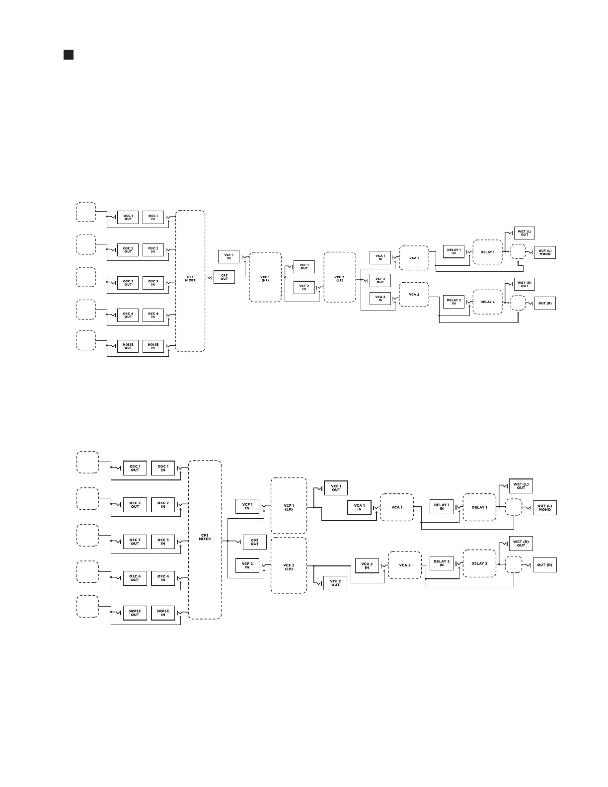
HP / LP SERIES
In this mode, VCF 1 is configured as a High Pass filter and VCF 2 is configured as a Low Pass filter.
Signal passes from the Mixer module out into VCF 1 OUT (High Pass), and then is routed into VCF 2 IN
(Low Pass). The mono output signal from VCF 2 feeds both VCA 1 IN and VCA 2 IN.
NOTE: This is the foundation for creating a Band Pass filter.
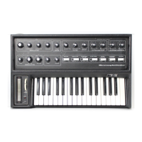
LP / LP STEREO
In this mode, VCF 1 and VCF 2 function independently as Low Pass filters. Both receive the same signal
from the Mixer module out. VCF 1 OUT is routed to VCA 1 IN, and VCF 2 OUT is routed to VCA 2 IN.
This creates a true-stereo signal path to the outputs.
FILTER MODE SIGNAL FLOW
OSC 1
OSC 2
OSC 3
OSC 4
NOISE
MIX
MIX
MIX
MIX
OSC 1
OSC 2
OSC 3
OSC 4
NOISE