Configuration
25
Please refer to “EC-MCB Wiring Diagram” on page 21 for information about properly terminat-
ing the CAN bus connection to display boards.
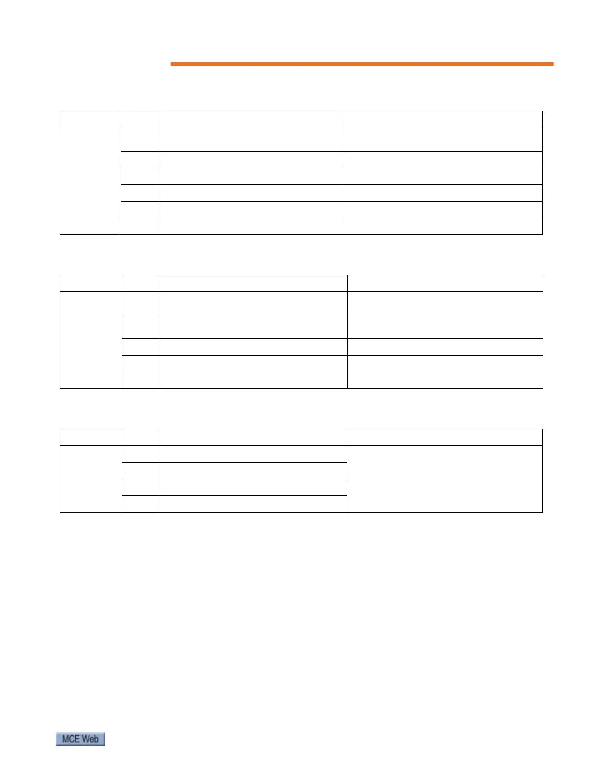
Table 7. EC-SCB Output Connector J9
Terminal No. Wye/Delta drive mode ATL and VVVF drive mode
J9
T13
Active when Up or Down contactors are
active
Active when UP or DOWN contactors are
active or when inverter output is active.
COM common common
T14 Spare output Not used
COM common common
T15 Spare output Not used
COM common common
Table 8. EC-SCB Connector J6
Terminal No. Component Remark
J6
CL1
Connect with the CANL terminal on the
EC-MCB
Communication between EC-MCB and EC-
SCB; lower entry display board (if
equipped); lower LCD panel (if equipped).
CH1
Connect with the CANH terminal on the
EC-MCB
24V+
DC24V power supply Note polarity. Connect correctly.
24V-
Table 9. EC-SCB Connector J7
Terminal No. Component Remark
J7
CH2
CAN
BUS +
Remote monitoring
CL2
CAN
BUS -
24V- -24VDC (not used)
24V+ +24VDC (not used)