Operating Adjustments
37
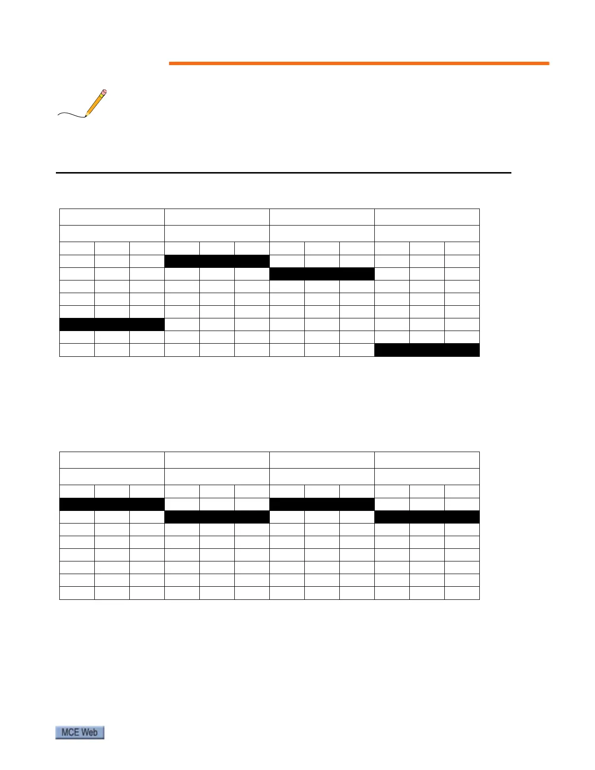
Parameters in the preceding table that reference this note are set by entering a number (1 - 7) in
the displayed digit that corresponds to the group of switches you want to set. For example,
entries shown in the tables below would result in the settings shown in the shaded area below
the entry.
• When set to 0, input latches
• When set to 1, input does not latch
• In this example, P24, 17, 16, 15, 14, and 13 are 0 (latching inputs) while P27, 18, 12, 11, 10,
and 9 are 1 (non-latching inputs)
• In this example, P37, 36, 33, 32, 31, 30, and 29 are 0 (latching inputs) while P34 and P28
are 1 (non-latching inputs).
Table 11. F4-13 Default Setting
Entry: 5Entry: 0Entry: 1Entry: 7
Switch Group D Switch Group C Switch Group B Switch Group A
P27P24P18P17P16P15P14P13P12P11P10P9
000
0 0 0 000000
001001
0 0 1 001
010010010010
011011011011
100100100100
1 0 1 101101101
110110110110
111111111
1 1 1
Table 12. F4-14 Default Setting
Entry: 0Entry: 1Entry: 0Entry: 1
Switch Group D Switch Group C Switch Group B Switch Group A
N/A N/A N/A P37 P36 P34 P33 P32 P31 P30 P29 P28
0 0 0 0000 0 0 000
000
0 0 1 0010 0 1
000010010010
000011011011
000100100100
000101101101
000110110110
000111111111