2-12 Maintenance
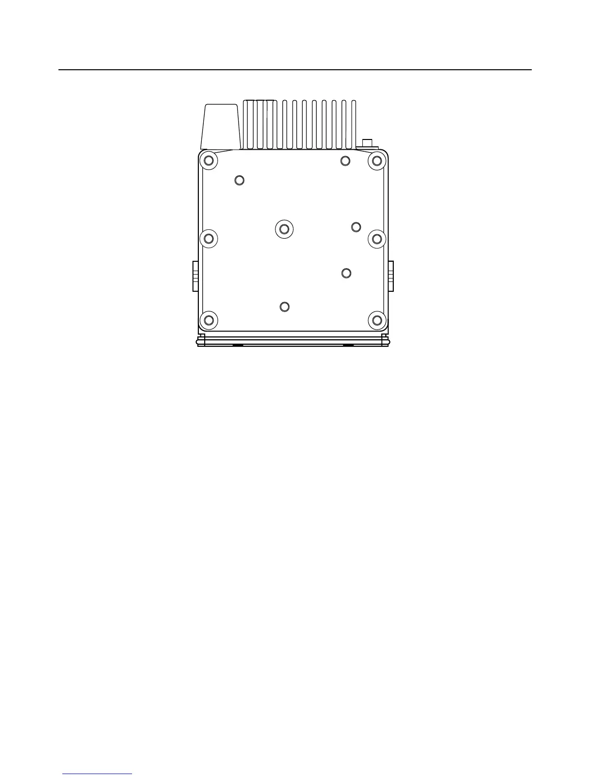
Figure 2-10: Top view of the LowBand radio chassis and die cast cover showing the screw sequence
2.7.4 Control Head Fitting
1. Align the “0” mark on the flex with the “0” mark on the chassis to the socket on the radio assembly
as shown in Figure 2-2.
2. Check that the back housing o-ring seal is undamaged and fitted in the groove. Replace the seal
if it is damaged (for more information, please see the exploded view diagrams and parts list
beginning in section "2.9 CDM750 Radio Control Head Exploded Mechanical View and Parts List"
on page 14 of this chapter).
3. Fit the back housing to the control head. Ensure that the tags on the back housing align with the
snap catch grooves on the control head. Press the back housing into place until it snaps into
place.
4. Check that the radio chassis o-ring seal is undamaged and fitted in the groove on the chassis
assembly. Replace the seal if it is damaged.
1
2
3
4
5
7
6
8
9

 Loading...


