Radio Programming and Tuning Procedures 4-3
4.3 Radio Tuning Setup
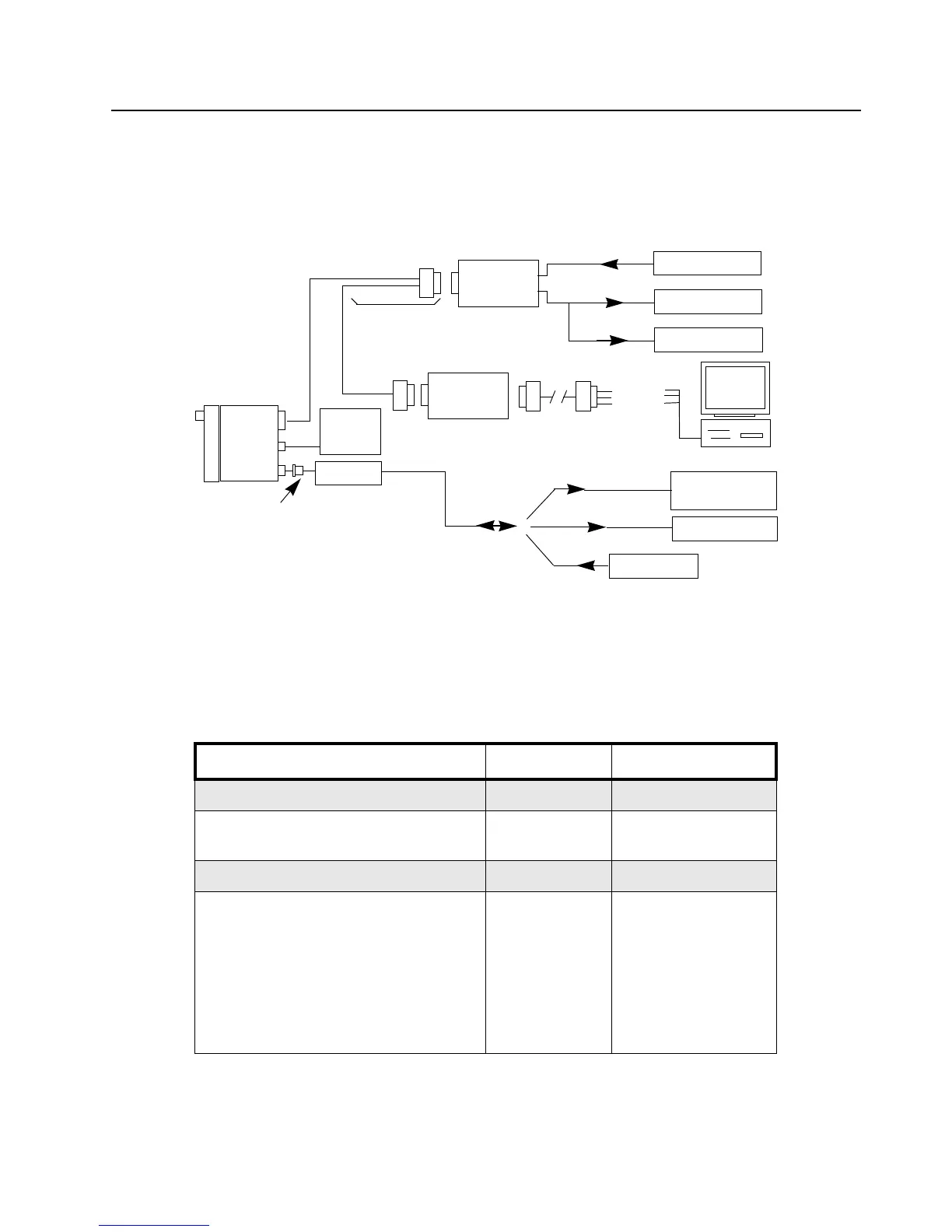
A personal computer (PC), Windows 95/98/NT, and a tuner program are required to tune the radio. To
perform the tuning procedures, the radio must be connected to the PC, radio interface box (RIB), and
test equipment setup as shown in Figure 4-4.
Figure 4-4: Radio Tuning Test Equipment Setup with External RIB
4.3.1 Initial Test Equipment Control Settings
The initial test equipment control settings are listed in Table 4-2.
Table 4-2: Initial Equipment Control Settings
Service Monitor Test Set Power Supply
Monitor Mode: Power Monitor Speaker set: A Voltage: 13.2Vdc
RF Attenuation: -70 Speaker/load:
Speaker
DC on/standby:
Standby
AM, CW, FM: FM PTT: OFF Volt Range: 20V
Oscilloscope Source: Mod
Oscilloscope Horizontal: 10mSec/Div
Oscilloscope Vertical: 2.5 kHz/Div
Oscilloscope Trigger: Auto
Monitor Image: Hi
Monitor BW: Nar
Monitor Squelch: mid CW
Monitor Volume: 1/4 CW
Current: 20A
Wattmeter
Audio Generator
Sinad Meter
AC Voltmeter
30 dB Pad
Audio In
Tx
Rx
Receive
Transmit
RF Generator
RIB
RLN-4008
RLN4460
Test B ox
Cable 3080369B72 (9 PIN)
Program/
AARKN4083
Te s t Cabl e
Service Monitor
or Counter
DB15
HLN8027
Mini UHF
Cable 3080369B71 (25 PIN)
Power
Supply
+13,2VDC
Rx Data
Gnd
Tx Data
to BNC
Radio
DC
RF
ACC
ZWG0130336-0

 Loading...


