3-1
Chapter 3
Transceiver Performance Testing
3.1 General
These radios meet published specifications through their manufacturing process by utilizing high-
accuracy, laboratory-quality test equipment. The recommended field service equipment approaches
the accuracy of the manufacturing equipment with few exceptions. This accuracy must be maintained
in compliance with the manufacturer’s recommended calibration schedule.
3.2 Setup
Supply voltage is provided using a 13.2Vdc power supply. The equipment required for alignment
procedures is connected as shown in the Radio Tuning Test Equipment Setup Diagram, Figure 4-4,
on page 4-3.
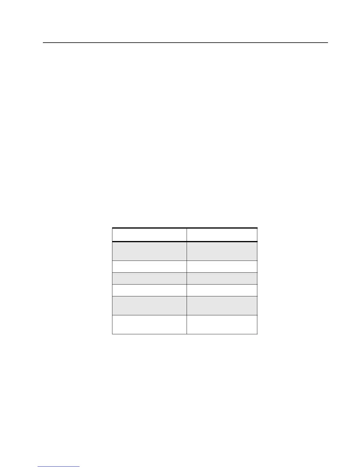
Initial equipment control settings should be as indicated in Table 3-1. The remaining tables in this
chapter contain the following related technical data:
Table 3-1: Table Chart
Table Number Title
3-2 Initial Equipment
Control Settings
3-3 Test Environments
3-4 Test Channel Spacing
3-5 Test Frequencies
3-6 Transmitter
Performance Checks
3-7 Receiver Performance
Checks

 Loading...


