6 Electrical connection
67BA6820378-03 EN
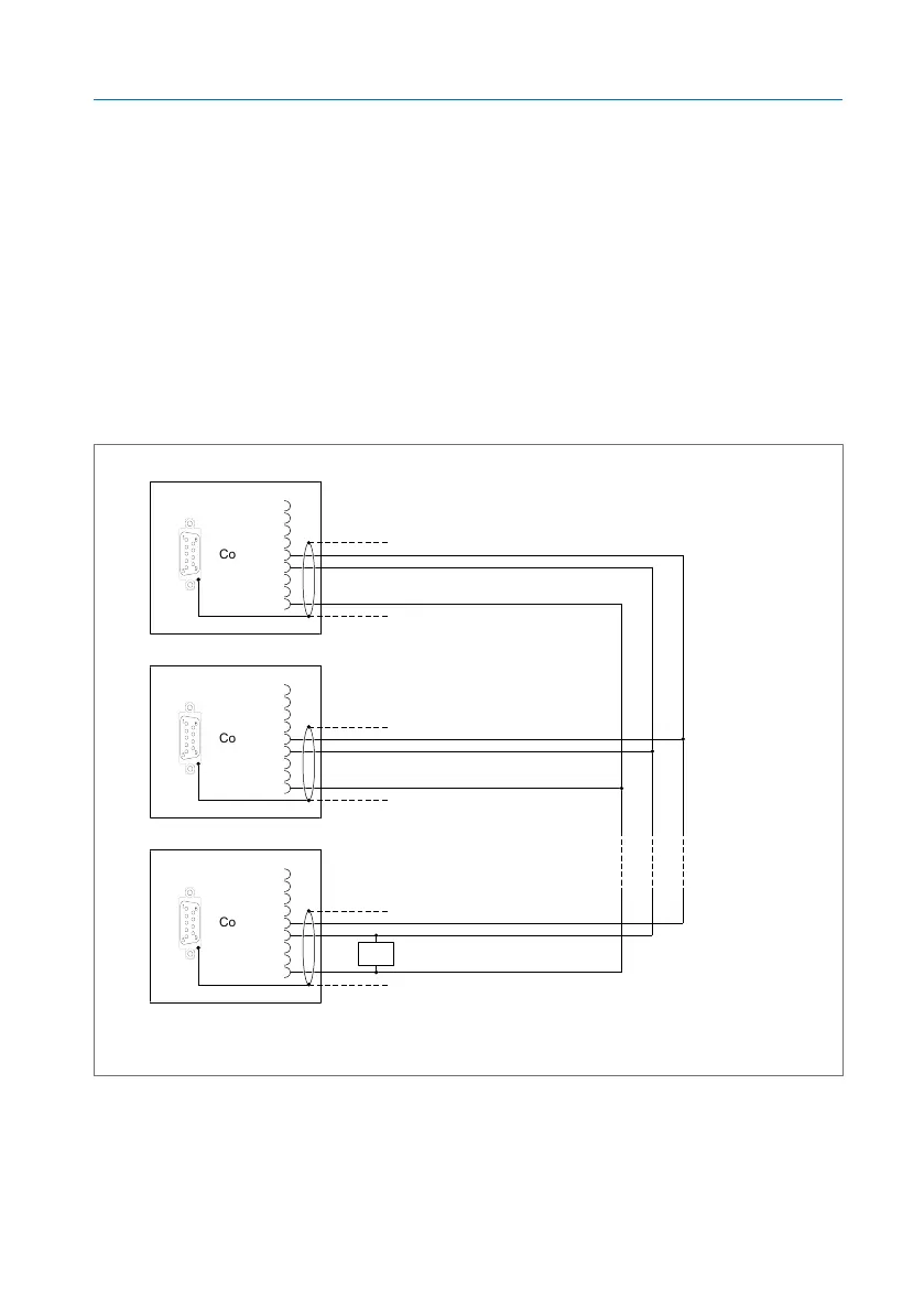
▪ You must connect the sensors via a shielded line with 3 conductors (D0,
D1, Common). The data lines (D0, D1) must be in twisted pairs. Note the
cable recommendation.
▪ Stub lines from the bus node to the respective device must be shorter
than 20m.
▪ The CPU assembly contains a terminating resistor (120Ω) at the COM2
interface. Install another terminating resistor (120Ω, 0.5W) at the other
end of the bus.
▪ The CPU assembly contains a pull-up resistor and a pull-down resistor
(each of 680Ω in accordance with the Modbus specification). No addi-
tional pull-up/pull-down resistors are needed.
CPU-COM2
Sensor 1
Sensor x
D0 (A)
D1 (B)
Com. (C)
1
2
3
4
5
6
7
8
9
D0 (A)
D1 (B)
Com. (C)
D0 (A)
D1 (B)
Com. (C)
120 Ω
Figure46: MR sensor bus