6 Electrical connection
66 BA6820378-03 EN
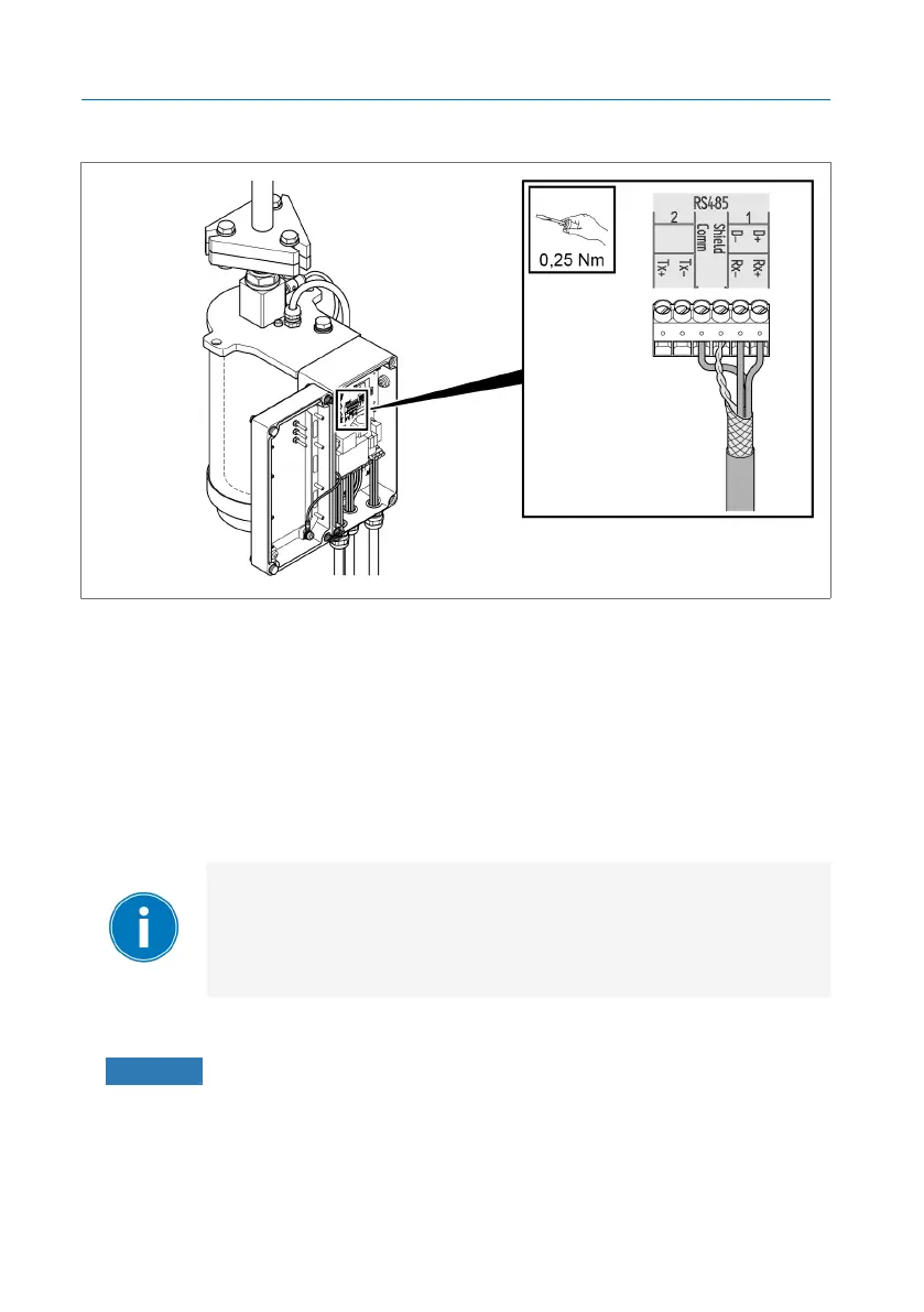
4. Twist the shielding, insert it into the "Shield" terminal and tighten.
Figure45: Connecting the half-duplex cable
6.9.3 Notes on connecting to the MR sensor bus
The optionally available MR sensor bus function lets you connect digital and
analog sensors to the device over Modbus RTU. The MR sensor bus sup-
ports the connection of up to 31 sensors (Modbus slaves). The ISM® device
operates as the Modbus master.
Ensure that no other Modbus master is connected over the
MR sensor bus. Assign a unique Modbus address to each
sensor you are connecting over MR sensor bus. The MR sen-
sor bus may experience errors if multiple sensors are using
the same Modbus address.
Observe the following notes for connecting the sensors:
▪ NOTICE! Damage to the device or sensor. Connect all of the sensors to
the potential equalization rail to avoid circulating currents over the MR
sensor bus.
▪ The MR sensor bus uses Modbus in a 2-wire configuration (2W). The 4-
wire configuration (4W) is not supported.