6 Electrical connection
54 BA6820378-03 EN
▪ The cables used must be flame-resistant in accordance with
IEC60332-1-2 or UL2556VW-1.
▪ If both low voltage and extra-low voltage are connected in the device, it
must be ensured that the circuits for extra-low voltage and for low voltage
in the connection area and in the cable are separated from each other
with double insulation.
Cable
*)
Terminal Cable type Cross-section
Protective conductor
connection
1 (PE)
Unshielded >= cross-section
of the voltage
supply terminal 2
(L+) and terminal
3 (N-)
Voltage supply 2 (L/+), 3 (N/-) Unshielded 1.5 … 4 mm² /
AWG 11 … 15
Regeneration signal-
ing relay, device error
signaling relay
4, 5, 6, 7, 8, 9 Unshielded 1.5 … 4 mm² /
AWG 11 … 15
Analog outputs: Ana-
log output 1, Analog
output 2
Terminals 10 to 15 Shielded 1.5 … 4 mm² /
AWG 11 … 15
RS485 Shielded 0.14 … 1.5 mm² /
AWG 15 … 26
Table5: Recommendation for connection cable (standard connections)
*)
It must be possible to load all connection cables with a nominal voltage of
300V;
Cable type solid or flexible
6.4 Routing and preparing the cable
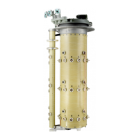
The glass cylinder of the Messko
®
MTRAB
®
can reach temper-
atures of >90°C during regeneration. When laying the cables,
ensure that they do not touch the glass cylinder.
Consider the position of the connections when preparing the cable.
Ensure that the length of the protective conductor (terminal
1) is at least 50mm longer than the supply voltage conductors
(terminals 2 and 3).