Introduction 1-3DXL5000 User and Technical Manual
connector, and a power fuse.
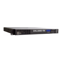
DXL5000 Receiver The rear panel of the DXL5000 Receiver
contains the I/O connectors, the AC input power connector, and
a power fuse.
1.6.3 Power Options
The DXL5000 System Transmitter and Receiver each operate
on the following AC power sources:
120/240 VAC, 50/60 Hz
Fuse ratings for the AC power sources are shown in Table 1-1.
Table 1-2: Receiver Fuse Ratings
Refer to the “Installation” Chapter on page 4-1 for additional
information.
1.6.4 Band and Frequency Options
The DXL5000 System can be ordered to cover the following
frequency bands.
• 1.99 GHz – 2.5 GHz (12/17MHz Channel)
• 4.94 GHz – 4.99 GHz (10MHz Channel)
Table 1-1: Transmitter Fuse Ratings
Operating Voltage Fuse Rating
120 VAC, 50/60 Hz 3.0A, 250V, Slow Blow
240 VAC, 50/60 Hz 3.0A, 250V, Slow Blow
Operating Voltage Fuse Rating
120 VAC, 50/60 Hz 1.0A, 250V, Slow Blow
240 VAC, 50/60 Hz 1.0A, 250V, Slow Blow
• 5.925 GHz – 6.425 GHz (10MHz Channel)
• 6.425 GHz – 6.525 GHz (25MHz Channel)
• 6.525 GHz – 6.875 GHz (10MHz Channel)
• 6.875 GHz – 7.125 GHz (25MHz Channel)
• 7.1 GHz – 8.4 GHz (20MHz Channel)
• 8.2 GHz – 8.5 GHz (19MHz Channel)
• 10.7 GHz – 11.7 GHz (40MHz Channel)
• 12.2 GHz – 12.7 GHz (24MHz Channel)
• 12.7 GHz – 13.25 GHz (25MHz Channel).
1.6.5 Mounting and Deployment Options
For fixed installation applications, the DXL5000 System
Transmitter and Receiver are usually mounted in a standard 19-
inch (48.3 cm) rack. Power is supplied by the site or facility
power source.
For more details on installation of the DXL5000 System, see the
“Installation” Chapter on page 4-1 for additional information.
1.6.6 System Integration
Once the DXL5000 System is installed, connected, and powered
up, system settings must be selected or modified using a PC or a
laptop computer. Changes to system settings can be performed
either locally or from a remote location via an Ethernet
connection.
1.7 DXL5000 Connections
For details on connections between DXL5000 Transmitter and
Receiver components, see the “Installation” Chapter on page 4-
1.
 Loading...