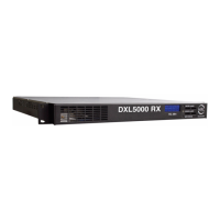
Operation 2-5DXL5000 User and Technical Manual
RSL dBm Display The RSL dBm 4-digit LED display indicates
the current receiver signal power level in dBm.
MAJOR ALARM LED When flashing amber, the MAJOR
ALARM LED indicates the PA is off and the summary alarm
relay has tripped; when amber, a major alarm has been detected
but no action has been taken.
MINOR ALARM LED When green, the MINOR ALARM LED
indicates no alerts are present; when amber, indicates an alert is
present; and when red, an alert is present and the alert relay has
tripped.
SCM STATUS LED When green, the SCM STATUS LED
indicates no alarms are present; when amber, a minor alarm is
present; and when red, as major SCM alarm is present.
POWER IN Connector The POWER IN power connector
provides connection to the removable external power cable. The
power connector assembly also contains the AC power fuse.
MGMT Connector The RJ-45 MGMT connector provides 10
Base T Ethernet connection for remote control.
IF OUT Connector The 75 ohm BNC female IF OUT connector
provides the 70 MHz IF output from the unit.
SUMMARY ALARM Connector The DB-15 SUMMARY
ALARM female connector provides summary alarm data for
common faults and events.
CHAN1 and CHAN2 DATA Connectors The CHAN1 and
CHAN2 DATA RJ-45 connectors provides 10/100 Base T
Ethernet connections to the unit.
CHAN1 and CHAN2 T1/E1 Connectors The CHAN1 and
CHAN2 T1/E1 RJ-45 connectors provide T1/E1 output
connections for channels 1 and 2.
ASI/DS3/E3 1 and 2 Connectors The ASI/DS3/E3 1 and 2
BNC 75 ohm female connectors provide ASI or DS3/E3 outputs
from the unit.
RF IN Connector The SMA 50 ohm female RF IN connector
provides the 70 MHz input from the external antenna.
RESET Switch When the RESET switch is pressed and held for
approximately 5 seconds, the IP address is reset to the factory
default IP address of 192.168.0.10, the subnet mask is reset to
the factory default subnet mask of 255.255.255.0, and the
default gateway is reset to the factory default subnet mask of
192.168.0.1. No other password or configuration settings are
effected.
ASI/SMPTE310 Connector The 75 ohm BNC female ASI/
SMPTE310 connector provides ASI or SMPTE310 outputs from
the unit.
DIV OUT Connector The 75 ohm BNC female DIV OUT
connector provides the diversity receive output from the unit.
IMC BUS Connector The IMC BUS DB-9 male connector
provides RS-232 or RS-485 inputs to the unit.
WAYSIDE DATA Connector The WAYSIDE DATA DB-9 male
connector provides connections for MPEG decoder Wayside
data.
DIV IN Connector The 75 ohm BNC female DIV IN connector
provides the diversity receive input to the unit.
2.3 Preparing for Operation
Each installation or deployment will have its own specific tasks
according to the application and the installed hardware.
2.3.1 Fixed Installation
For fixed installations, the DXL5000 System is typically mounted

 Loading...