Installation 4-4DXL5000 User and Technical Manual
CAUTION
Power supply cords and cables must be
protected. Do not run cords where they can
be walked upon. Protect cables against
pinching and chafing. Pay special attention
to locations where the cables enter or exit
an enclosure or make a sharp bend.
CAUTION
Ensure that the electrical supply is protected
by over current protection devices, as
required by the applicable electrical codes.
• Secure all cables at close intervals along their entire
lengths.
• Protect the cabling with additional sheathing or padding
anywhere it passes through a hole or lays against an
obstruction.
• Provide flex relief at any location where the cable must
change direction sharply, to maintain a smooth bend and
prevent kinking.
• Provide strain relief at each connector to absorb any
pulling forces on the cable and to prevent damage to the
connector.
4.6 Power Connections
4.6.1 Power Requirements
The DXL5000 Transmitter and Receiver have the following
power requirements.
Supply Voltage: 120/240 VAC, 50/60 Hz
Transmitter:
Power Consumption: 130 watts nominal
Receiver:
Power Consumption: 50 watts nominal
4.6.2 Power Supply and Distribution
AC power is supplied externally, from the facility power source.
Power is distributed to the DXL5000 Transmitter and Receiver
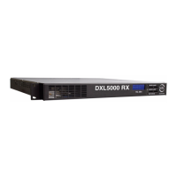
through the rear panel AC POWER IN connector. See Figure 4-
2.
Figure 4-2: POWER IN Connector
The DXL5000 Transmitter and Receiver do not contain power
switches to control application of power to the units. Power to
the units is controlled directly from the power source.
Power Connections MRC supplies an AC power cable with
each DXL5000.
Additional Powering Notes Check the electrical source to
ensure it can provide all the power needed at the site without
overloading. Power ratings for equipment can be found on a
rating plate, usually on the rear panel. If necessary, consult a
licensed electrician.
MGMT
I
F
I
N
I
F
M
O
N
SUMMARY ALARM
IMC BUS WAYS
CH
D
POWER IN
Connector