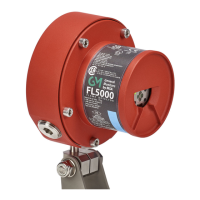
22 FL5000 Multi-Spectrum Flame Detector US
5 Installation
5 Installation
CAUTION!
The FL5000 contains components that can be damaged by static electricity. Always wear grounding apparel when
handling or installing the unit.
Failure to follow this caution can result in minor or moderate injury.
The basic steps in a typical installation are listed in the sections below. The installation process may vary depending on the
exact site configuration.
• Only personnel trained and qualified in the HART communication protocol may install and use the HART
configuration of the FL5000 detector.
• Only trained and authorized users can configure the FL5000.
• The FL5000 flame detector is to be installed in accordance with NFPA 72 requirements.
• When used with certified fire alarm control units equipped with 4-wire smoke detector circuits, the FL5000 should be
reset by temporarily removing the supply voltage for at least 70 ms with a decline of operation voltage of no less than
3 VDC.
5.1 Unpacking Equipment
All equipment is packaged in shock absorbing containers that protect against physical damage. The contents should be
carefully removed and checked against the enclosed packing list.
If any damage has occurred or there is any discrepancy in the order, please contact MSA.
NOTE: Each FL5000 is completely tested at the factory; however, a system check is required upon initial start-up to
guarantee system integrity.
Sustainability Tip:
Be sure to recycle the FL5000 packaging according to your local environmental regulations.
5.2 Required Tools
Tool Use
5 mm Allen wrench Fasten / remove front assembly from base (not included)
Flat-head screwdriver 3/16 inch (5 mm) maximum Connect wires into the Terminal Block (not included)
Adjustable wrench To make conduit and cable gland connections (not included)
Torque wrench (needed if mounted)
To tighten the mounting clamp (the torque spec is 50 ft-lbs so a
17mm or 11/16' wrench is required)
5.3 Detector Location Guidelines
Several variables are involved in selecting locations to install detectors. The following guidelines should be considered in
regard to particular conditions at the site where the unit(s) is being installed:
• 5.3.1 Optical Sensitivity Range
• 5.3.2 Detector Field of View
• 5.3.3 Environmental Factors