5 Installation
US FL5000 Multi-Spectrum Flame Detector 27
5.5 Field Wiring Procedure
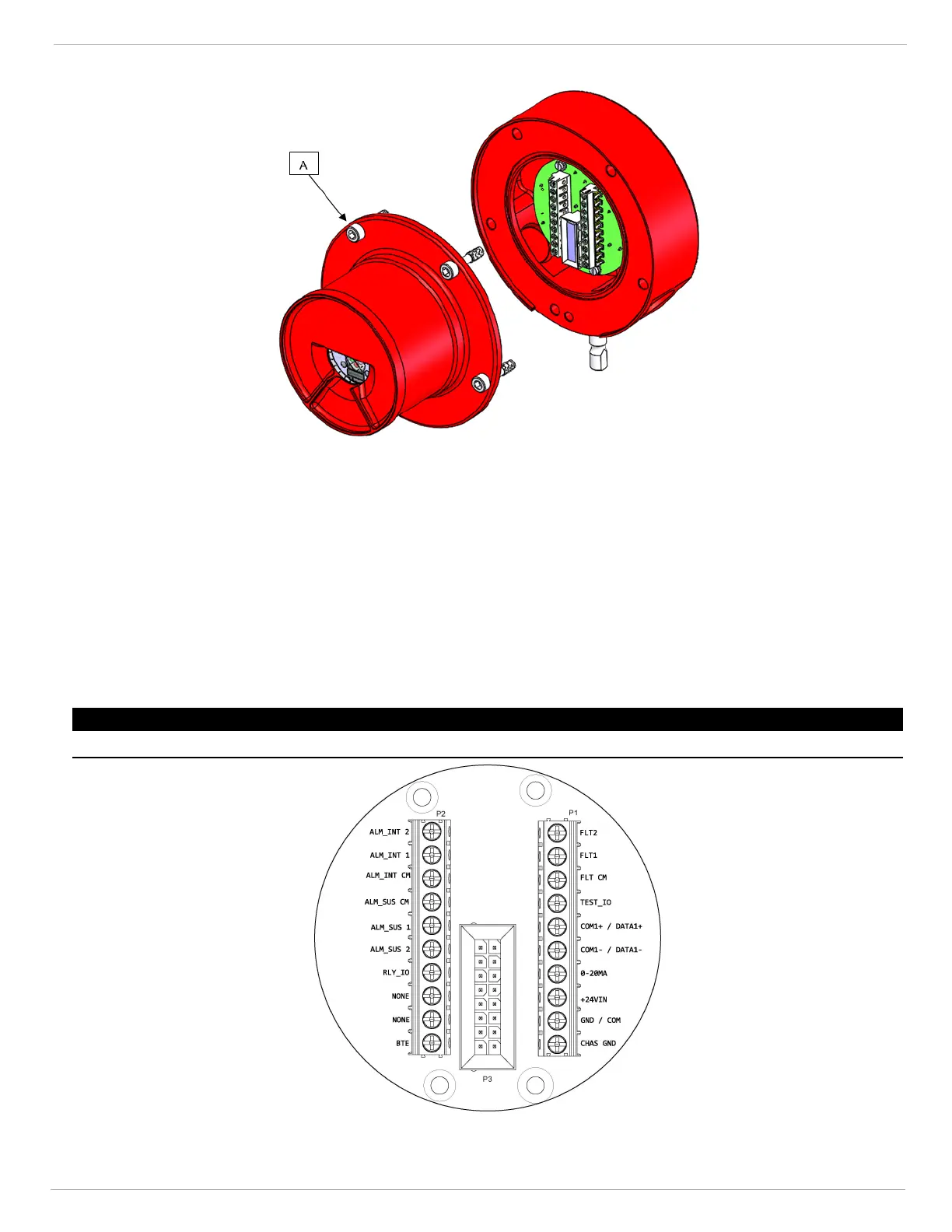
Figure 13 FL5000 Housing
1. Loosen the captive screws (A) located on the Optical Housing Assembly.
2. Pull the Optical Housing Assembly from the Base Housing Assembly to separate, gently rock from side to side if
necessary to loosen the connector's grip.
3. Make all necessary wiring connections as described in 5.6 Terminal Connections. For an example of wiring, please
refer to the connection diagram.
4. Set switch selectable options as described in 5.7 Switch Selectable Options.
5. Fit the Optical Housing Assembly to the Base Housing Assembly.
6. Tighten the captive screws (A) located on the Optical Housing Assembly.
7. Check 1 Safety Regulations f or warnings and wiring requirements.
NOTICE
Do not unscrew the field wiring board from the base housing assembly for wiring.
Figure 14 Terminal Connections