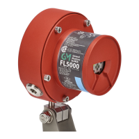
36 FL5000 Multi-Spectrum Flame Detector US
5 Installation
5.8 Powering the FL5000
After connecting to a 24 VDC power source, the unit will go through the following on power up:
• all four LEDs (red, yellow, blue, green) will blink in a series for 15 seconds
• the unit will output an analog signal of 0 mA (3.5 mA with HART or 1.25 mA for HART with small current enabled)
• the fault relay will be in the de-energized state
If the unit is configured with relays energized, the relays will de-energize for approximately 0.5 seconds. Upon completion
of the power on sequence, the green LED will alternate - on for 5 seconds and off for 0.5 seconds to indicate a READY
status.
Refer to 3.3 Bluetooth Connectivity for steps to connect via Bluetooth upon power up.
5.9 Power Up Grounding of the Test and Relay Reset Lines
During power up, grounding the reset relay line for approximately 1 second forces the Modbus parameters on both
channels to go to their default values of: 19,200 Baud, 8-N-1 format, Unit ID = 1 and HART short ID will reset to 0.
During power up, grounding the test line for approximately 1 second forces the unit to use the dipswitch settings rather than
use the settings stored in the flash memory. These settings are for the energized/de-energized relay state, the alarm delay,
and the unit sensitivity.