28 FL5000 Multi-Spectrum Flame Detector US
5 Installation
5.6 Terminal Connections
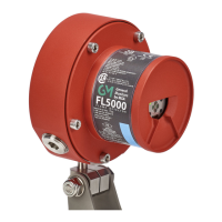
Figure 15 Wire-Strip Lengths
All wire connections are made through the ¾ inch (1.9 cm) NPT openings in the Base Housing to the Terminal Block. The
Terminal Block is located in the Base Housing Assembly and accepts 14 AWG (2.08 mm
2
) to 22 AWG (0.33 mm
2
)
stranded or solid-core wire. Each wire should be stripped as shown in the figure above.
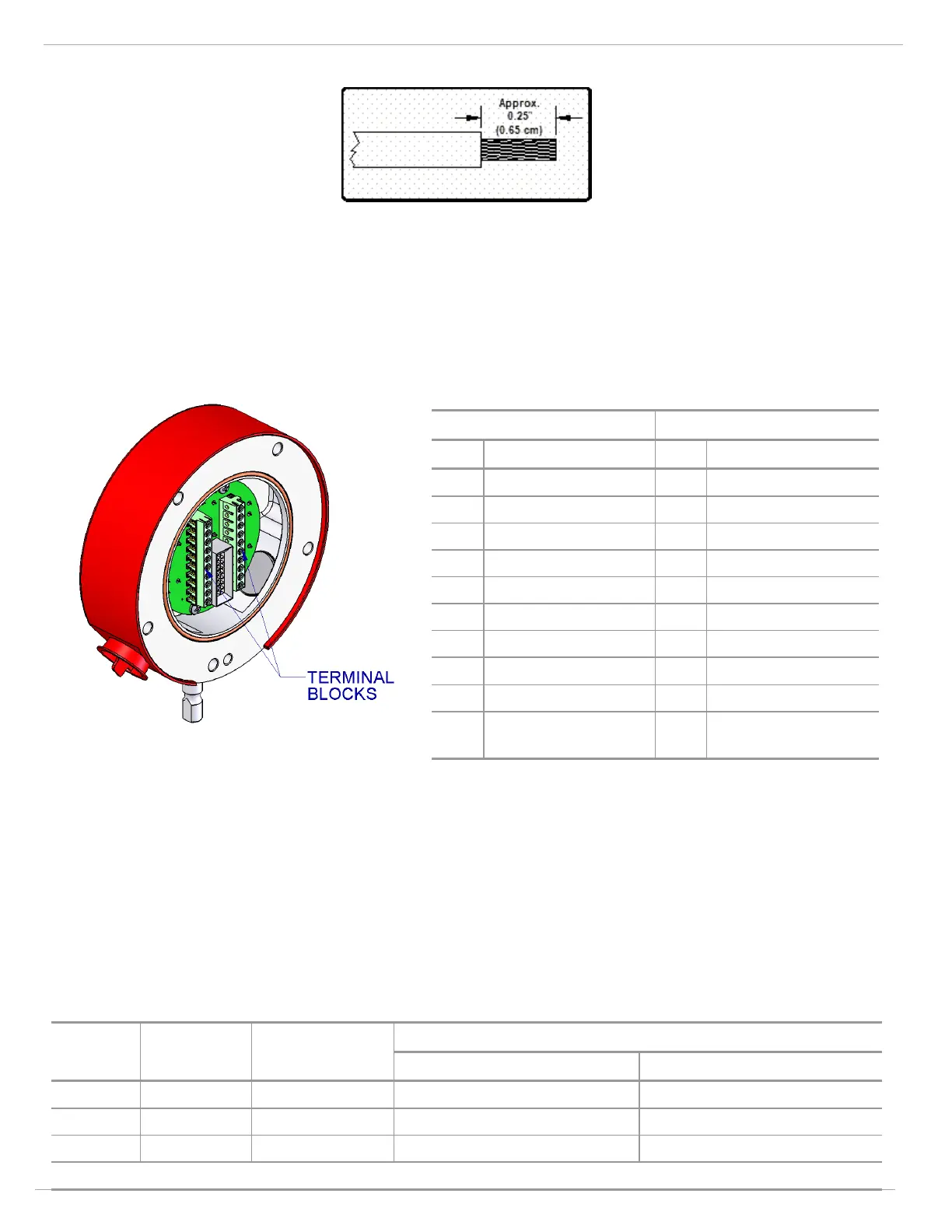
To connect the wire to the Terminal Block, insert the conductor into the connection space and tighten the corresponding
screw terminal.
Figure 16 Base Housing and Terminal Blocks
There are twenty possible terminal connections:
Terminal Block - P2 Terminal Block - P1
Pin # Description Pin # Description
10 ALM_INT 2 1 FLT 1
9 ALM_INT 1 2 FLT 2
8 ALM_INT CM 3 FLT CM
7 ALM_SUS CM 4 TEST_IO (Test Mode)
6 ALM_SUS 1 5 COM1+/DATA1+
5 ALM_SUS 2 6 COM1-/DATA1-
4 RLY_IO (Relay Reset) 7 0-20 mA
3 NONE 8
+24 V
in
2 NONE 9 GND/COM
1 BTE 10
CHGND/CHASGND
(Chassis Ground)
NOTE: The FL5000 is backward compatible with the FL4000H. The user can use the top head of the FL5000 plug to plug
into the existing base of the FL4000H.
The following sections provide a description and specification for each connection:
• 5.6.1 Sustained Alarm Relay
• 5.6.2 Instant Alarm Relay
• 5.6.4 Fault Relay
5.6.1 Sustained Alarm Relay
Terminal
Block
Connection
Point
Block Name
User Relay Settings
Normally De-energized Normally Energized
P2 Term 5 ALM_SUS 2 Sustained Alarm NO Sustained Alarm NC
P2 Term 6 ALM_SUS 1 Sustained Alarm NC Sustained Alarm NO
P2 Term 7 ALM_SUS CM Sustained Alarm Common Sustained Alarm Common
NOTE: NO = Normally Open; NC = Normally Closed