30 FL5000 Multi-Spectrum Flame Detector US
5 Installation
3 DCControl Voltage 7 117 VACControl Voltage
4
Protection circuit for relay contacts when switching a
DCload.
8
Protection circuitt for relay contacts when switching an
ACload
Refer to the figure in 5.6.1 Sustained Alarm Relay for all relay connections.
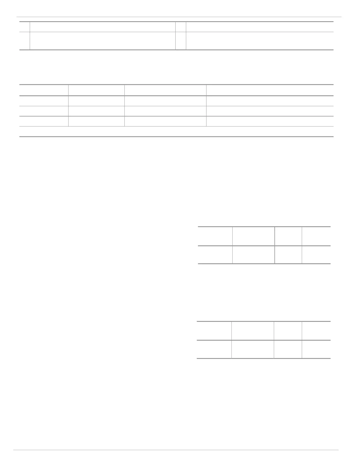
5.6.4 Fault Relay
Terminal Block Connection Point Block Name Normally Energized
P1 Term 1 FLT 2 Fault NC
P1 Term 2 FLT 1 Fault NO
P1 Term 3 FLT CM Fault Common
NOTE: NO = Normally Open; NC = Normally Closed
These connections are to the SPDT FAULT relay. The FAULT output configuration is normally energized and non-latching.
This is the standard output configuration and it cannot be changed.
The FAULT circuit will be activated during the time-out function, a low power or loss of power condition, or during a failed
COPM check. During these conditions, the FAULT relays will de-energize and the analog output signal will drop to 0 mA (2
mA for COPM Faults, 3.5 mA with HART or 1.25 mA for HART with small current enabled) for the duration of the FAULT.
The FAULT relay contact rating is 8 A @ 24 VDC.
Refer to the figure in 5.6.1 Sustained Alarm Relay for all relay connections.
5.6.5 Alarm Reset Terminal
The RESET, when activated, returns a latched SUSTAINED
ALARM and/or INSTANT ALARM output that is no longer valid to
its original state.
Terminal
Block
Connection
Point
Block
Name
Setting
P2 Term 4 RLY_IO
Relay
Reset
For this RESET function, place one contact of a SPST (single pole, single throw), normally open, momentary switch to P2
Terminal 4 and the other contact to P1 terminal 9 (GND).
To activate, press and release the switch.
5.6.6 Test Mode Terminal
By connecting one contact of a SPST, normally open, momentary
switch to P1 terminal 4 and the other contact to P1 terminal 9
(GND), the user can put the unit into a special test mode.
Terminal
Block
Connection
Point
Block
Name
Setting
P1 Term 4
TEST_
IO
Test
Mode
NOTE: When in test mode via ground wire, the Test
Lamp triggers a “ready” condition only.
When the switch is first closed, the mode is set and the FL5000 goes to 1.5 mA or 3.5 mA with HART and small HART
current disabled (ready mode) and remains at this value while detecting the Test Lamp. The relays are not activated.
Closing the switch a second time or after approximately 3 minutes, the unit will return to normal operation.