5 Installation
US FL5000 Multi-Spectrum Flame Detector 29
The connections are to the single pole, double throw (SPDT) SUSTAINEDALARM relay. SUSTAINEDALARM output is
time delayed for 0, 8, 10, or 14 seconds. This time delay can be set by Modbus (RS-485) or the user selectable dipswitch
per 5.7 Switch Selectable Options.
Note that a minimum time delay of 8 seconds can be applied if the flame source is removed within 50% of set delay time
from the start of flame. Please refer to 5.7.1 Time Delay Settings. If set via Modbus below 8 seconds, the detector may
go into alarm even if the flame source is removed within 50% of the delay time.
The SUSTAINED ALARM output can be normally energized or de-energized, latching or non-latching, and these options
are also set via Modbus or by a dipswitch. The SUSTAINED ALARM relay contact rating is 8 A @ 24 VDC. Refer to the
figure in 5.6.1 Sustained Alarm Relay for all relay connections.
5.6.2 Instant Alarm Relay
Terminal
Block
Connection
Point
Block Name
User Relay Settings
Normally De-energized Normally Energized
P2 Term 8 ALM_INT CM Instant Alarm Common Instant Alarm Common
P2 Term 9 ALM_INT 1 Instant Alarm NC Instant Alarm NO
P2 Term 10 ALM_INT 2 Instant Alarm NO Instant Alarm NC
NOTE: NO = Normally Open; NC = Normally Closed
Description: These connections are to the SPDT INSTANT ALARM relay. The INSTANT ALARM output is immediate on
the FL5000. The INSTANT ALARM output can be normally energized or de-energized, latching, or non-latching. These
options are also set via Modbus or by a dipswitch per 5.7 Switch Selectable Options. The INSTANT ALARM relay contact
rating is 8 A @ 24 VDC.
Refer to the figure in 5.6.1 Sustained Alarm Relay for all relay connections.
5.6.3 Alarm Wiring Relay Protection
Inductive loads (bells, buzzers, relay, contractors, solenoid valves, etc.) connected to the Sustained Alarm, Instant Alarm,
and Fault relays must be clamped down as shown on diagrams in 5.6.2 Instant Alarm Relay. Unclamped inductive loads
can generate voltage spikes in excess of 1000 volts. Spikes of this magnitude will cause false alarms and possible
damage.
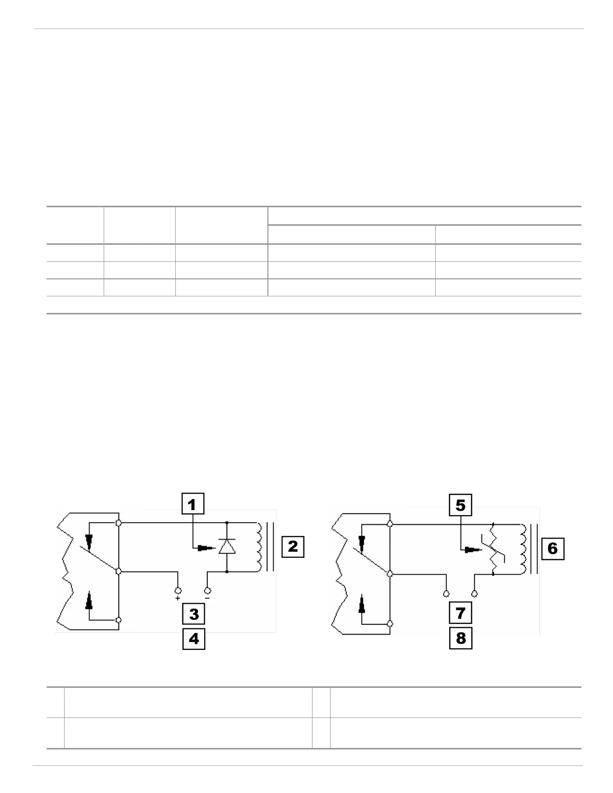
Figure 17 Relay Contacts
1
General Purpose Rectifier Diode. 1N4005 or
Equivalent (Note Polarity)
5
Metal Oxide Varistor Rated for 150 VRMS, General
Electric V150LA20A or Equivalient
2
Switched LoadCoil -Bell, Buzzer, Relay, Contactor,
Solenoid, Valve, etc.
6
Switched LoadCoil -Bell, Buzzer, Relay, Contactor,
Solenoid, Valve, etc.