5 Installation
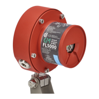
US FL5000 Multi-Spectrum Flame Detector 31
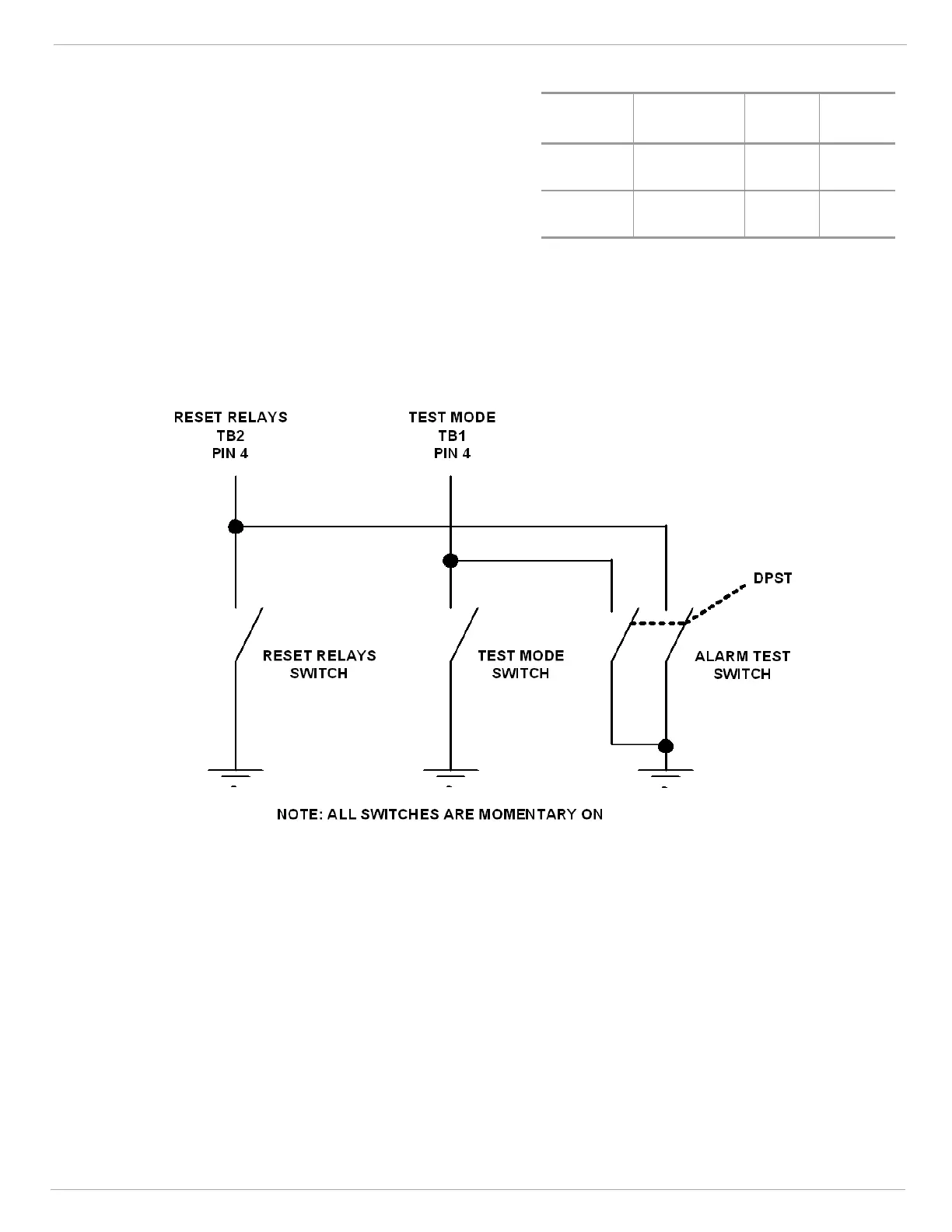
5.6.7 Alarm Test Terminals
By connecting one contact of a DPST, normally open, momentary
switch to each of the P1 terminal 4 and P2 terminal 4
simultaneously and the other contact to (GND), the user can
perform an Alarm Test per the figure below.
Terminal
Block
Connection
Point
Block
Name
Setting
P1 Term 4
TEST_
IO
Test
Mode
P2 Term 4 RLY_IO
Relay
Reset
NOTE: The latching INSTANT ALARM and / or
SUSTAINED ALARM will have to be reset manually.
Activating this switch for 0 to 14 seconds, depending on the alarm time delay settings, can test the alarm outputs of the
Flame Detector. The Alarm Test will activate the INSTANT ALARM and SUSTAINED ALARM relay outputs as well as
the appropriate analog output.
The device will remain in this state until the switch is released or until 3 minutes has elapsed.
Figure 18 Wiring Diagram - Reset Relays, Test Mode &Alarm Test