32 FL5000 Multi-Spectrum Flame Detector US
5 Installation
5.6.8 Analog Output
Terminal Block Connection Point Block Name Setting
P1 Term 7 0 - 20 mA Analog Output
The 0 to 20 mA output is a current signal that corresponds to the following:
Analog Output HART (1.25 mA)* HART (3.5 mA) HART Disabled/OFF
Startup 1.25 mA 3.5 mA 0 to 0.2 mA
FAULT Signal 1.25 mA 3.5 mA 0 to 0.2 mA
Test Mode 1.5 mA 3.5 mA 1.5 ± 0.2 mA
COPM Fault Signal 2.0 mA 3.5 mA 2.0 ± 0.2 mA
Ready Signal 4.05 ± 0.2 mA 4.05 ± 0.2 mA 4.05 ± 0.2 mA
INSTANT ALARM Signal 16.0 ± 0.2 mA 16.0 ± 0.2 mA 16.0 ± 0.2 mA
SUSTAINED ALARM Signal 20.0 ± 0.2 mA 20.0 ± 0.2 mA 20.0 ± 0.2 mA
Bluetooth Load 3.0 mA 3.0 mA 3.0 mA
* HART (1.25 mA) is the default.
NOTE: Refer to the FL5000 Modbus or HART manual for Current Range selection.
• The maximum analog output load is 600 Ω.
• The COPM Fault Signal may also be set to 0 mA at the factory (non HART only).
• Startup mode lasts exactly 15 seconds.
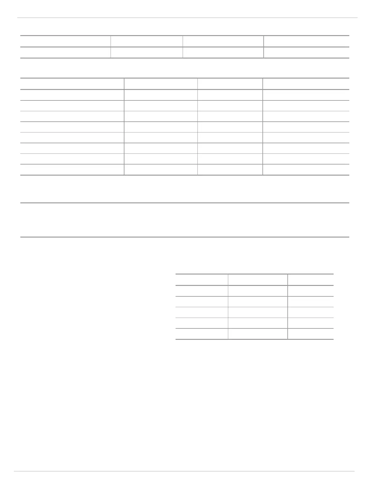
5.6.9 Cable Requirements
0 - 20 mA
For interfacing with 250 Ω input impedance devices,
the following maximum cable lengths apply (maximum
50 Ω loop):
AWG Feet Meters
14 4,500 1,370
16 2,340 715
18 1,540 470
20 970 300
22 670 205
NOTE: When Ex d cable glands are utilized, shielded cable must also be used.