5 Installation
US FL5000 Multi-Spectrum Flame Detector 33
5.6.10 Power
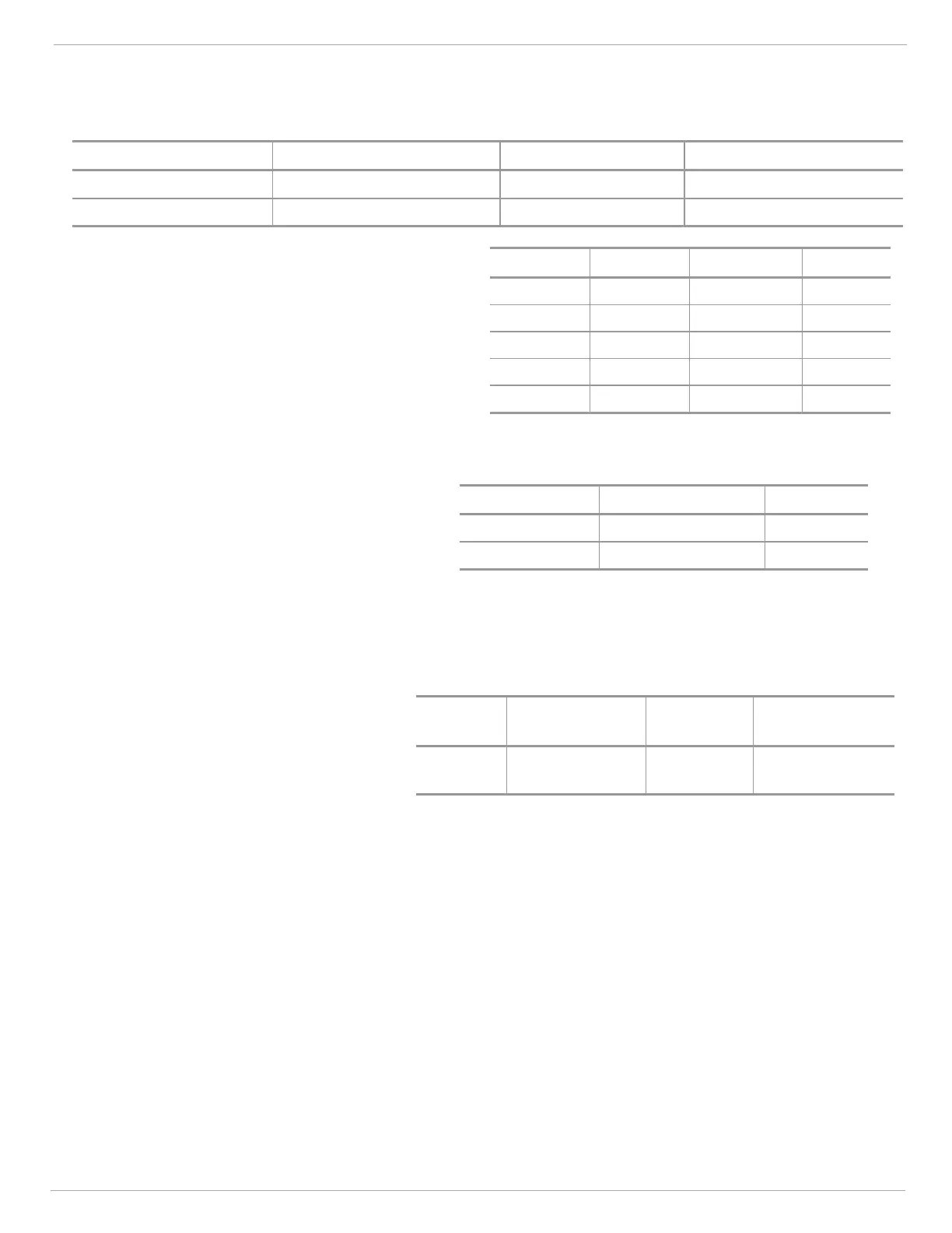
The table below shows the power connections for the FL5000. The supply voltage range is 20 to 32 VDC at the detector
(low voltage is detected at 18.5 VDC).
Terminal Block Connection Point Block Name Setting
P1 Term 8 +24 Vin +24V
in
(VDC)
P1 Term 9 GND/COM Ground (COM)
The following maximum cable lengths apply
for a +24 VDC supply (maximum 12 Ω loop):
AWG mm
2
Feet Meters
10 5.27 6,289 1,917
12 3.31 3,956 1,207
16 1.31 1,565 478
18 0.823 984 300
20 0.519 620 189
5.6.11 Modbus (RS-485) Output
The connections for the Modbus output are shown.
The Modbus connection is used to either query the
unit’s status or to configure the unit. For detailed
information on Modbus protocol, consult the FL5000
Modbus Manual.
Terminal Block Connection Point Setting
P1 Term 5 COM1+(A)
P1 Term 6 COM1- (B)
5.6.12 Chassis Ground
For proper operation of the detector, the
FL5000 must be grounded through a wire to
the chassis.
The table shows the terminal block and
connection point for the chassis ground
terminal. Failure to establish a ground
connection can lead to greater susceptibility of
the detector to electric surges, electromagnetic
interference, and ultimately, damage to the
instrument.
Terminal
Block
Connection
Point
Block
Name
Setting
P1 Term 10
CHGND/
CHASGND
Chassis Ground