12 SENTRY io US
2 Overview
l
Relay 1 is pre-programmed as common alarm
l
Relay 2 is pre-programmed as common fault
l
Relays 3 and 4 are user configurable
NOTE: The SENTRY io provides only normally de-energized relay coils. The only exception is the common fault relay
which is normally energized.
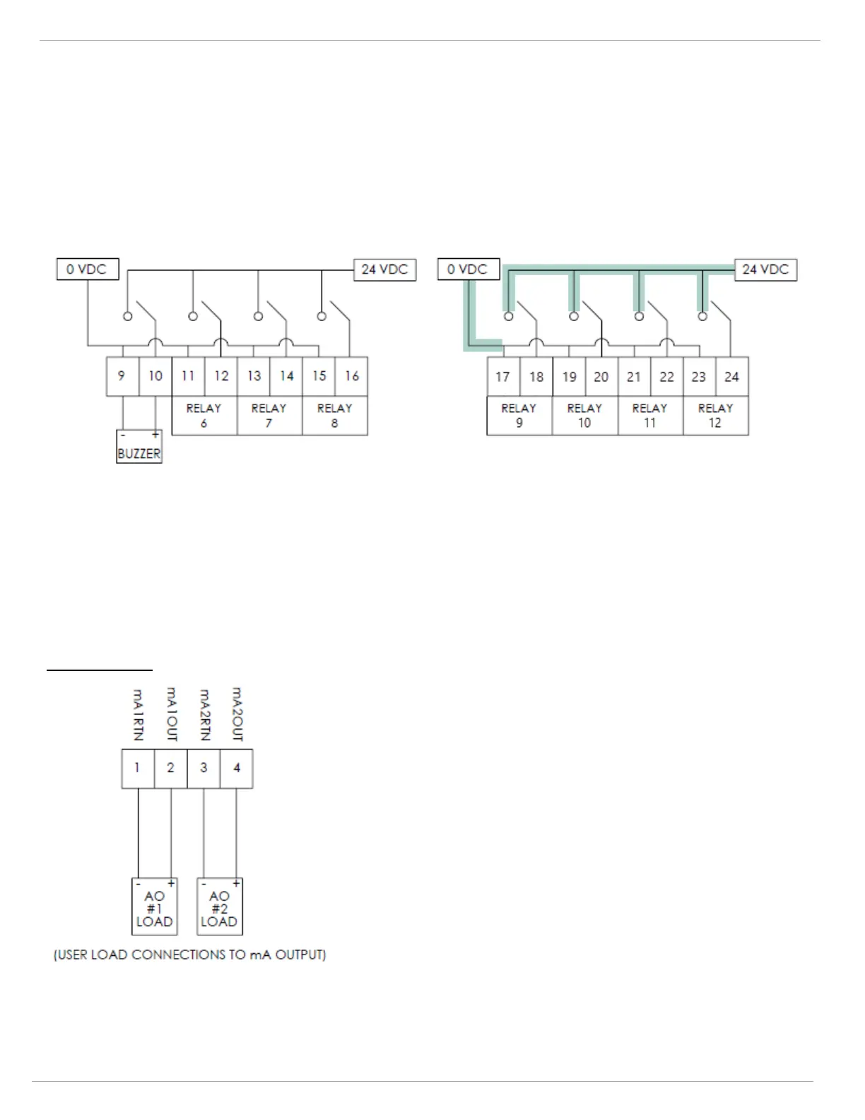
The SENTRY io comes pre-wired with all contacts dry except for relays 5-8 (which includes the buzzer on relay 5). To add
additional powered relays, you need to connect 0 VDC and 24 VDC to the terminal strip as shown below. Powered contacts
are used for things like horn and strobe activation.
Module 2, relays 5-8 are powered contacts.
This image displays the existing pre-wired powered
contacts.
This image displays the typical modifications to provide
additional powered contacts. The highlighting indicates the
customer-added wiring.
The SENTRY io also supports optional analog 4-20 mA signal outputs. These signals are current sources and should be
used with sinking signal receivers only. These signal outputs are used to retransmit the analog input signals to another
control system. These analog outputs are a 1:1 mapping of all the input analog signals to the SENTRY io. Analog signal
outputs are sourced using the internal 24 VDC power supply.
Analog Outputs