14 SENTRY io US
2 Overview
2.6 Field Cabling
Adhere to local building codes and individual field device recommendations when wiring the SENTRY io on site.
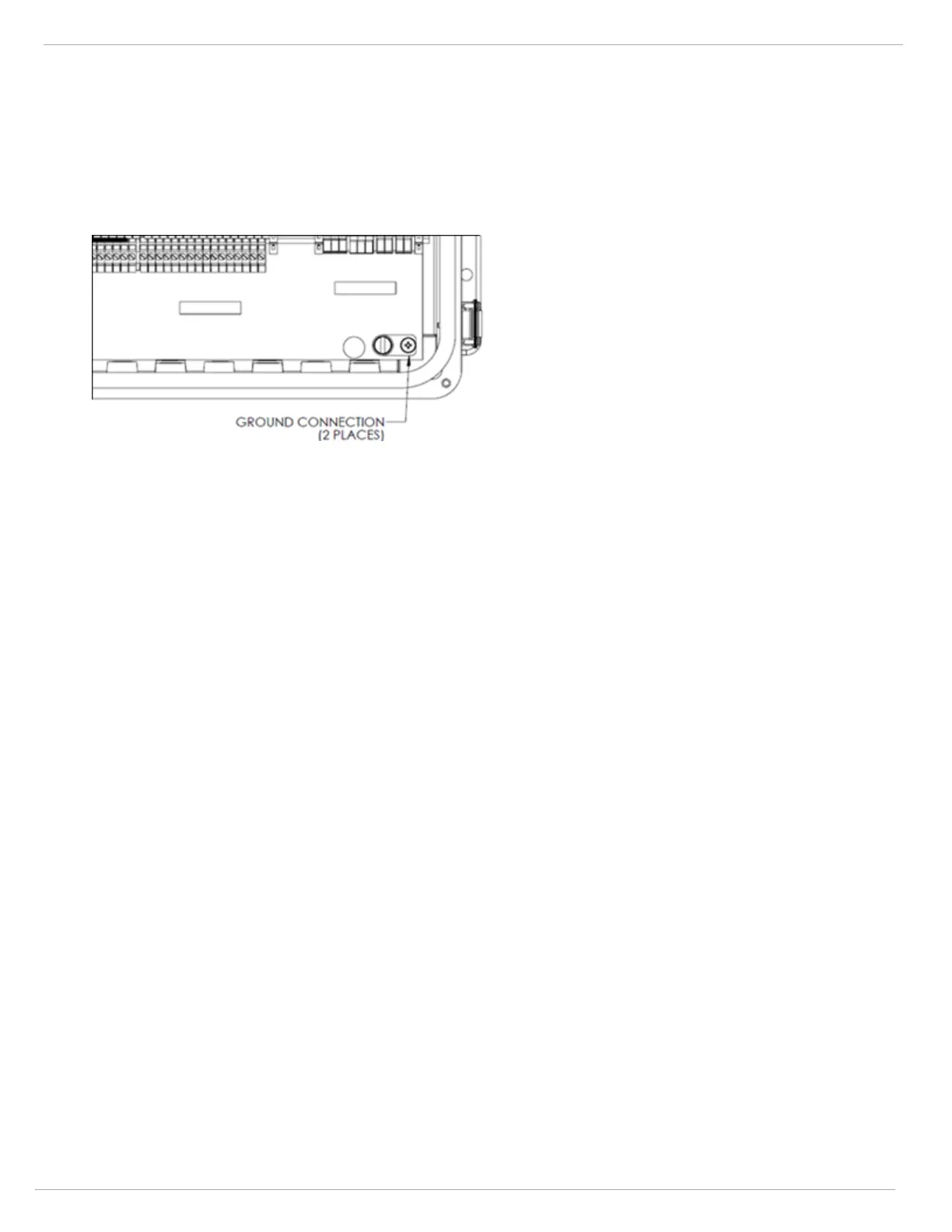
Cable shielding for all input and output devices must be connected to SENTRY io chassis ground.
NOTE: SENTRY io terminal blocks can accept a maximum wire gauge of 12 AWG and a minimum gauge of 18 AWG, one
wire per terminal.
l
Earth ground—Make solid ground connection to one of the panel ground lugs
l
Panel power input cabling
o
120 or 220 VAC acceptable
o
Orange power shut-off knife switch is included within panel power terminals
l
Field device signal input cabling
o
Analog 4-20mA current signals—Recommended type is stranded copper 3-conductor with overall foil shield
NOTE: Do not exceed the maximum loop impedance of the analog input and analog output channels listed in 7
Technical Specifications.
o
Discrete Input signals—Recommended type is stranded copper 2-conductor
l
Field device output cabling
o
Relay output signals—Recommended type is stranded 2-conductor with overall foil shield
NOTE: Be aware of voltage drop on DC cable runs. Select proper cable size to prevent excessive voltage
drop.
o
Analog 4-20mA current signals—Recommended type is stranded copper 3-conductor with overall foil shield
l
Digital Communications cabling
o
Modbus RTU—Should utilize a twisted shielded cable. Belden 3105A cable or similar cable is acceptable.
o
Modbus TCP/IP—Should utilize CAT 6 Ethernet cables
o
Device Level Ring (DLR)—Can be implemented using either copper or fiber media. Contact MSA Customer
Support for assistance with DLR implementations.
l
Expansion enclosure cabling may be required
2.7 Configuration and Programming
System configuration and programming is accomplished using the SmartStart configuration wizard on the 7-inch
touchscreen located on the door of the SENTRY io panel. To simplify configuration and programming of your system, it is
recommended to plan and document each of the following identifiers for all connected field devices and operational
relationships between each input and output device: