18 SENTRY io US
3 Installation
l
Use an approved 3-conductor wire (minimum 14 AWG), rated 300 VAC at 221°F (105°C), to complete the AC power
connection.
l
Use only conduit hubs and hardware that are suitable for fiberglass enclosures.
3.4.2 Electrical Installation Procedure
To wire the SENTRY io:
1. Disconnect electrical power.
2. Release the two latches on the right side of the SENTRY io and open the enclosure.
3. Attach the ESD wrist strap to the ESD connection point inside the enclosure.
4. Remove the AC power wiring hole plug.
5. Install conduit hubs that are suitable for fiberglass enclosures and rated for both environmental and hazardous areas
classifications.
6. Put the AC power wiring through the conduit.
7. Connect the AC power wiring to the #1 AC terminal block (HOT) and #2 AC terminal block (NEUTRAL) input
terminals. Make sure the connectors are seated securely.
8. Connect the AC power ground wire to the ground lug so the SENTRY io chassis ground is connected to the earth
ground.
9. Close the enclosure and latch the two latches.
10. Supply electrical power to the SENTRY io.
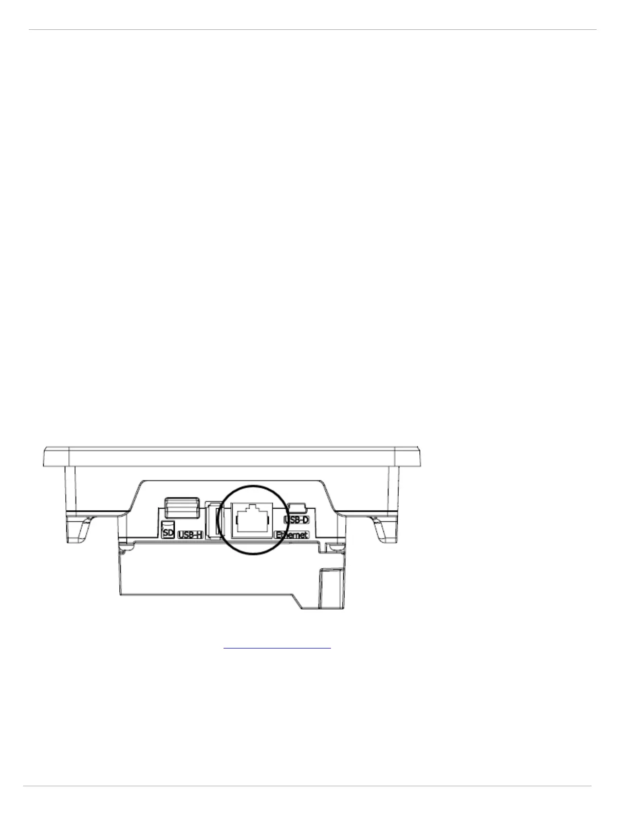
3.5 Communications
3.5.1 Modbus TCP
The SENTRY io comes standard with Modbus TCP communication. The Ethernet port is located on the side of the touch
screen inside the enclosure.
The SENTRY io Modbus address list includes addresses for discrete alarms, discrete inputs, relays, voting zones, system
faults, and analog. View this section in the SENTRY io Online Help to download the spreadsheet.
3.5.2 Modbus RTU (RS485 Serial)—Optional
The SENTRY io has an available Modbus RS485 capability by adding the optional communication module—P/N:
10221943.
The RS485 module clips on to the back of the SENTRY io touchscreen.